Temperature Sensors
The kit includes three digital temperature sensors, identical save the lug hole size (M4, M5, and M8).
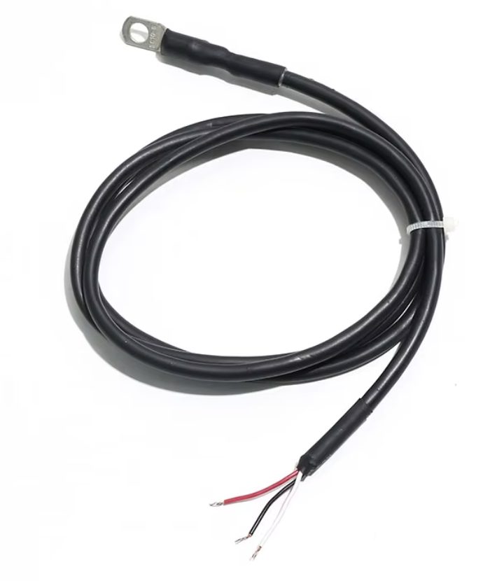
Mount one of the sensors to the alternator's case. A 10 kΩ thermistor can optionally be used instead.
One of the other sensors goes on a battery terminal, for battery temperature. A battery temperature already published on NMEA 2000 (PGN 127508), by a VE.Direct battery monitor fitted with a temperature sensor, or by an RV-C source can be used in place of the probe.
Battery temperature is used for hot and cold charge lockout, voltage control loop gain derating at low battery temperatures, and for the ability to transmit PGN 127508 on the NMEA 2000 bus.
To use the separate Battery Temperature Sensor, and "Extra Temperature Sensor", wire each or both in parallel with Alternator Temperature, and they will be disambiguated in software. These sensors are limited to 125 °C max, so EGT is not a good idea unless it is post-dilution with water. Cylinder head, engine room, bilge, etc. should be fine.
Any unused sensors can be kept as spares. Contact X Engineering for additional spares, they are a couple of dollars each, or you can buy DS18B20s from many suppliers.
Mounting to the alternator
- Pick a bolt or stud on the alternator case, as close to the stator (copper laminations sometimes visible) as practical. That is the hottest accessible metal.
- Use grounded case hardware only. Do not mount the lug on the output stud (B+).
- Remove the nut or bolt, slip the lug on, and retighten. The lug should sit metal-to-metal against the case — no washers between the lug and the case.
- Route the lead clear of the belt, pulleys, and exhaust components, and secure it for strain-relief.
Wiring
Each sensor has three bare 24 AWG leads. They connect to Cable 1:
| Sensor lead | Cable 1 pin | Cable 1 wire | Function |
|---|---|---|---|
| Red | 1 | Orange/White | 3.3 V power |
| Black | 2 | Orange | Ground |
| White | 3 | Green/White | Signal |
The complete pinout for all four cables is in Data Cables & Pinout.
Battery Temperature Options
Battery temperature has to be measured at the bank. Use one of the two remaining ring-lug probes, or a battery temperature published on NMEA 2000, VE.Direct, or RV-C. With no measured source, the cold and hot charge lockouts never fire and the voltage loop leaves its battery-temperature gain derate at 1.0.
What you need
- One of the two remaining ring-lug probes.
- A straight-through RJ45 splitter.
- An Ethernet patch cable long enough to reach from the regulator to the battery, plus a short one from the regulator to the splitter if the splitter you pick is all jacks.
- Three adhesive-lined butt splices (HSWBS-10, 26–24 AWG) and five to cap the conductors you do not use.
Choosing the splitter
The splitter has to pass all eight pins straight through to every jack — pin 1 to pin 1, pin 2 to pin 2, and so on. Three that do:
| Splitter | Part | Ports | Approx. |
|---|---|---|---|
| Victron Energy RJ45 Splitter, 1 Male to 2 Female | ASS030065510 | plug on a 150 mm lead, 2 jacks | $19 |
| L-com Modular TEE Junction (8x8)F / (8x8)F, (8x8)F | TDS1039-8C | 3 jacks | $20 |
| L-com Splitter, 5 RJ45 (8x8) Fully Wired | JMOD4U-1 | 5 jacks | $30 |
The Victron carries its own 150 mm lead, so its plug reaches the regulator and the body hangs clear. The two L-com parts are all jacks, so they need one more short patch cable, regulator to splitter, on top of the run out to the battery. Both L-com parts are stocked by Mouser and DigiKey under the same part number as well as by L-com direct.
Avoid a splitter whose plug is molded straight into the body with no lead. It sits hard against the regulator and its jacks cover the neighboring ports.
The other common kind of RJ45 splitter divides the pairs between the two jacks — pins 1, 2, 3 and 6 to one, pins 4, 5, 7 and 8 to the other, remapped onto 1, 2, 3 and 6 there. Anything sold as carrying "two 10/100 devices over one cable", or that has to be fitted in pairs at both ends of a run, is this kind. It cannot work here. The alternator branch would lose the tachometer and both current-sensor pins, and pins 1, 2 and 3 of the battery branch would carry the stator tap, 5 V and the current-sensor signal instead of power, ground and the sensor data line — which would destroy the probe wired to them.
Parallel connections
Install the splitter at the regulator, so the battery run begins from there instead of doubling back from the alternator first.
Both jacks carry the same eight signals.
Put a small amount of dielectric grease in each jack of the splitter and on the plug faces before you mate them, the same as any other connector on the boat. Keep it off the butt splices — the adhesive lining needs a clean surface to seal to.
Wiring the new branch cable
One end of the branch cable plugs into the splitter. Cut the other end off, strip the jacket back about 60 mm, and only use three of the eight conductors.
| Branch cable pin | Wire (T568B) | Probe lead |
|---|---|---|
| 1 | Orange/White | Red — 3.3 V |
| 2 | Orange | Black — ground |
| 3 | Green/White | White — signal |
Cap the other five. Crimp each into one end of an HSWBS-10 and heat it — the adhesive seals the empty end, and the gauge is an exact match. HL8-22-14 is the purpose-made closed-end cap if you would rather have one.
Mounting at the battery
Bolt the ring lug to the battery's negative terminal, or to a grounded stud within a few inches of it.
Do not mount it on the positive terminal. On a bank of several batteries, guess the one in the warmest position — usually the middle of the group or the one furthest from ventilation.
Secure the lead so it cannot chafe.
Extra Temperature Sensor
The third probe mounts wherever you want a temperature you can see and alarm on — a battery compartment, a refrigeration space, the engine room itself. It never acts on charging.
It joins the same three wires as the other two, either at the splitter with a second branch cable or spliced into the branch you have already run. Either way the wiring is identical to the battery branch above: pin 1 to the red lead, pin 2 to black, pin 3 to white, all three probes in parallel.
All three sit on one bus and are told apart by serial number, not by which branch they arrive on, so there is nothing to configure at the wiring end. Assign it the Extra role in the table below. It has high and low alarm limits under Setup → Alarms → Temperature Alarms, and it can be published to NMEA 2000 as its own temperature instance (Temperature message, PGN 130312) from Setup → Integrations.
Cable length
Keep the total of all sensor wires under 50 ft (15 m), including the length of Cable 1, plus the length of the branch cable(s), plus the probe leads themselves.
Assigning parallel sensor identities
The regulator identifies each probe by its serial number, so a new probe has to be told what it is measuring.
- Open Setup → Temperature → Temperature Sensors. Every probe on the bus is listed by serial number with its live reading.
- Warm one probe in your hand and watch which row moves. That is how you tell them apart.
- Set that row's Role to Battery or Extra.
- Switch on the matching Battery temperature probe or Extra temperature probe toggle beneath the table. The role tells the regulator which probe is which; the toggle is what lets that reading be used.
The same table appears during commissioning under Commissioning Prerequisites → Digital Temperature Sensors, where the column is called Measures. There, choosing Battery or Extra also switches the matching probe toggle on, so that one step does both.
Thermistor
The regulator also accepts a 10 kΩ thermistor as an alternative temperature source (not recommended — the digital sensor is more accurate where it matters, and retains an extra ground for other purposes). Other thermistor resistances are possible with an on-board resistor change.
The full comparison of sensor options, including an untested but interesting analog alternative, is in Hardware → Sensors → Temperature Sensors.