Current Sensor
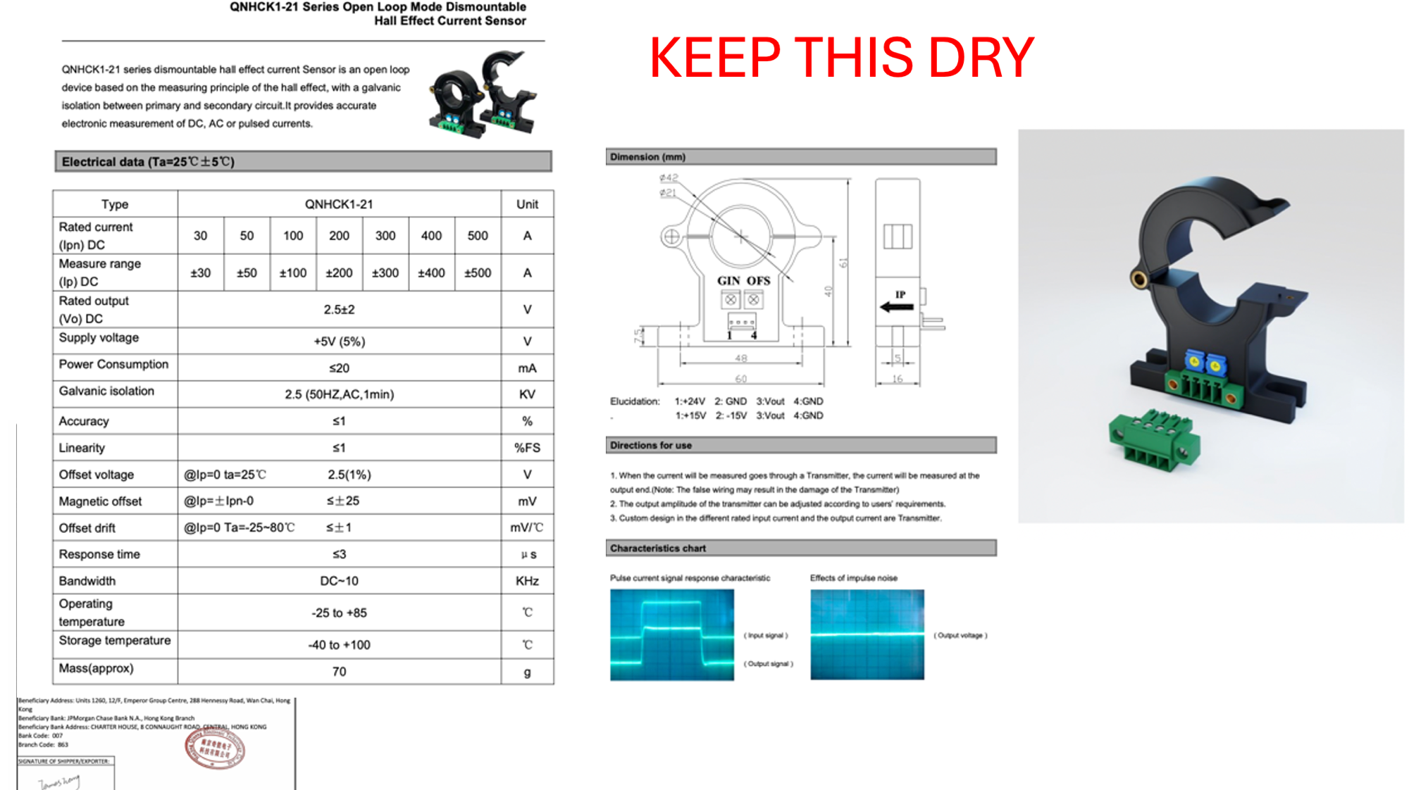
Part: QNHCK1-21 — Open Loop Hall Effect Current Sensor, dismountable. The 300 A version ships standard; 200 A and 500 A variants are supported by a firmware setting. Galvanically isolated output; measures DC, AC, or pulsed current.
Mounting and wiring instructions are in Installation → Sensors → Current Sensor. This page is the technical reference.
Why an open-loop Hall sensor
A traditional shunt requires breaking the high-current path and inserting a precision resistor — every connection is a failure point carrying full alternator output, and the measurement leads sit at battery potential. The Hall clamp avoids all of that: the cable passes through uncut, the sensor output is galvanically isolated (2.5 kV) from the conductor, and the sensor can be added to or removed from an existing installation without touching the high-current wiring.
The trade-off is accuracy — roughly 1% for this sensor versus 0.1%-class for a good shunt. For field control purposes that is more than sufficient: the control loop needs a fast, stable current signal, not laboratory absolute accuracy. (Battery current, where coulomb-counting accuracy does matter, is measured separately by the precision battery monitor (INA228) and its shunt — see BatteryV and Current Monitor.)
Specifications (300 A version, shipping standard)
| Parameter | Value |
|---|---|
| Rated current | 300 A DC |
| Measure range | ±300 A |
| Output voltage | 2.5 V ± 2 V |
| Supply voltage | +5 V (±5%) |
| Power consumption | ≤ 20 mA |
| Galvanic isolation | 2.5 kV |
| Accuracy | ≤ 1% |
| Response time | ≤ 3 µs |
| Bandwidth | DC – 10 kHz |
| Operating temperature | −25 to +85 °C |
Output scale: 0 A → 2.5 V midpoint. Full positive (300 A) → 4.5 V. Full negative (−300 A) → 0.5 V. Linear across the full range (6.7 mV per amp). The 200 A and 500 A variants use the same 2.5 V ± 2 V output swing — only the amps-per-volt scale differs.
How the regulator reads it
The sensor output lands on analog input channel 1 (AIN1) of the analog front end, carried on Cable 1 along with the sensor's 5 V supply and ground — pin assignments in Data Cables & Pinout.
Alternator current feeds the fastest control loop in the regulator, so this channel gets priority in the analog sampling schedule — roughly two hundred samples per second, several times the rate of the other analog channels. The full signal chain (op-amp buffering, protection, ADC configuration) is documented in Analog Inputs.