Installation
Alternator Type
Before wiring, determine whether your alternator is P-type (high drive) or N-type (low drive). This dictates which field terminal you connect to and which jumper you install on the board.
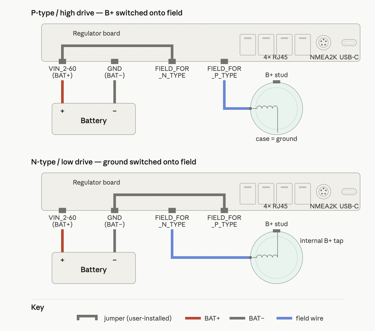
P-type alternator (high drive)
A P-type alternator has the field winding's far end internally bonded to the alternator case (chassis ground). The single field wire emerging from the regulator-side brush is switched to B+ by the regulator to excite the field.
- Field wire to: field-positive terminal (FIELD_FOR_P_TYPE)
- Jumper installed: BAT+ input to drain (VIN_2-60 ↔ FIELD_FOR_N_TYPE)
- External clamp module: not required
- External field fuse: not required — the board's input protection covers the field path
Field current path (output on):
battery (+) → board BAT+ input (VIN_2-60) → jumper → Q3 → field-positive terminal (FIELD_FOR_P_TYPE) → field wire → field winding → alternator case → engine ground → battery (−)
N-type alternator (low drive)
An N-type alternator has the field winding's far end internally tied to B+ (typically at the alternator's diode trio or an internal B+ tap on the rectifier). The single field wire emerging from the regulator-side brush is switched to ground by the regulator to excite the field.
- Field wire to: field-negative terminal (FIELD_FOR_N_TYPE)
- Jumper installed: source to ground (FIELD_FOR_P_TYPE ↔ GND)
- External clamp module: required — see Appendix A of the Alternator Field Drive doc
- External field fuse: required, sized to the alternator's rated field current
Field current path (output on):
battery (+) → alternator B+ stud → internal tap → field winding → field wire → field-negative terminal (FIELD_FOR_N_TYPE) → Q3 → jumper → board ground (GND) → battery (−)
Note
In N-type mode, field current does not pass through the regulator's BAT+ input (VIN_2-60). The board sees no field current on its protected supply rail.
Quick reference — alternator type
| P-type / high drive | N-type / low drive | |
|---|---|---|
| Field wire to | FIELD_FOR_P_TYPE | FIELD_FOR_N_TYPE |
| Jumper | VIN_2-60 ↔ FIELD_FOR_N_TYPE | FIELD_FOR_P_TYPE ↔ GND |
| Regulator switches | B+ onto field | Ground onto field |
| External clamp module | Not required | Required |
| External field fuse | Not required | Required |
Wire and Jumper Sizing
Installer responsibility
This regulator is sold without a harness. You are responsible for your own wire selection and fusing. This section gives you the guidance to make those decisions correctly.
Field current — what to expect
Most alternator installations draw less than 10 A of field current. Larger-frame alternators (200 A+) sometimes push toward 8–10 A. Anything beyond that is unusual and typically indicates dual-alternator or specialty applications. The regulator's design ceiling of 10 A gives margin for most real-world installations.
A note on duty cycle: An alternator rarely operates at 99–100% PWM duty in practice. The regulator backs off duty cycle as the battery accepts charge, and most operating life is spent at 30–70% duty. Voltage drop across the field wiring is not a meaningful concern — a small drop just means the regulator commands slightly higher duty cycle to compensate, which it has plenty of headroom for. Size wire for safety and code compliance, not voltage drop.
Connector ratings — the technical ceiling
The PCB-side connector is the Cixi Kefa Elec KF2EDGK-5.08-04P-AA, rated 15 A at 320 V. The mating plug is the Kangnex WJ2EDGRC-5.08-04P-14-00A, rated 10 A at 300 V. The lower of the two — 10 A continuous — is the system's hard limit.
For installations under 10 A field current (the typical case) you are operating within all ratings comfortably. For installations approaching or exceeding 10 A, see the high-current installations section below.
Standard installation — under 10 A field
- Wire: 14 AWG marine-grade stranded tinned copper, Type II or Type III stranding per ABYC E-11.
- Wire termination: Plain stranded wire under the screw — no ferrule. In this connector style the screw cage compresses bare strands more uniformly than a rigid ferrule; individual strands deform around the cage geometry for more total contact area. A ferrule is rigid; bare strands conform.
- Jumper: The supplied Phoenix Contact EBP 3-5 (p/n 1733172) with the middle blade snapped out gives a 2-position bridge with 10.16 mm prong spacing — exactly matching the regulator's terminal layout. Each blade is 2.0 mm wide × 0.5 mm thick. Phoenix rates the bridge at 12 A continuous.
The jumper blade and the harness wire share a single wire entry hole at one terminal (VIN for P-type, GND for N-type). The 0.5 mm-thick blade lies flat against one wall of the hole; the 1.6 mm-diameter wire stacks alongside it. The screw cage clamps both.
To install:
- Insert the blade flat into the wire entry hole.
- Strip 8 mm from your harness wire and insert it into the same hole, alongside the blade.
- Torque the screw to 0.5–0.6 N·m.
- Tug-test the wire firmly. If it pulls free, something is wrong — re-seat and repeat.
Wire ampacity reference (ABYC E-11)
Stranded tinned copper, single conductor:
| Wire size | Engine-space ampacity | Outside engine-space ampacity |
|---|---|---|
| 16 AWG | 10 A | 15 A |
| 14 AWG | 15 A | 20 A |
| 12 AWG | 20 A | 25 A |
| 10 AWG | 30 A | 40 A |
For US-only installations, NEC chassis-wiring tables allow ~15% higher ampacities. Designing to ABYC ensures the installation passes survey and remains safe in marine engine compartments.
High-current installations — over 10 A field
You only need this section for unusual loads: dual alternators in parallel from one regulator, very large-frame alternators (300 A+), or industrial/commercial alternators with field draws outside the marine norm.
Warning
Running the Kangnex connector above its 10 A rating is at your discretion and shortens connector life. For sustained high-duty operation above 10 A, consider sourcing a higher-rated mating plug.
If you proceed:
- Wire: 12 AWG marine-grade tinned stranded. The Cixi Kefa connector accepts up to 14 AWG max, so 12 AWG is at the edge of what fits.
- Jumper: At currents above 10 A, the EBP bridge is operating near its 12 A rating with no thermal margin. Better to splice the jumper directly into your harness wire. For P-type: splice a short branch of 12 AWG off the BAT+ conductor and run it into the FIELD_FOR_N_TYPE terminal. For N-type: splice from BAT− to FIELD_FOR_P_TYPE. The Y-splice goes inside heat-shrink near the regulator end of the harness. This eliminates the EBP from the high-current path; only your wire and the connector body carry load.
Voltage drop reference
Informational only — the regulator compensates via PWM duty cycle, so even the high end of this table doesn't meaningfully degrade alternator output. Useful for sanity-checking only.
12 V system, one-way drops:
| Wire | 10 A, 12 ft | 15 A, 12 ft | 10 A, 24 ft | 15 A, 24 ft |
|---|---|---|---|---|
| 14 AWG | 0.30 V | 0.45 V | 0.60 V | 0.90 V |
| 12 AWG | 0.19 V | 0.29 V | 0.38 V | 0.58 V |
| 10 AWG | 0.12 V | 0.18 V | 0.24 V | 0.36 V |
Fusing — your responsibility
The installer is responsible for sizing and installing all fuses. Two fuses are required:
1. Field circuit fuse — required on the field wire for all installations. Size to your alternator's rated maximum field current — typically 10 A for standard installations, 15 A for high-current applications. Use the alternator manufacturer's spec sheet to confirm.
N-type installations
In N-type mode, field current flows from the alternator's own B+ stud through the field winding and into the regulator's GND, bypassing the regulator's input protection entirely. Without a dedicated field fuse, the field wiring and alternator field winding are unprotected against a fault. This fuse is mandatory for N-type installations. P-type configurations are partially protected by the regulator's input protection, but a field fuse is still good practice.
2. Battery feed fuse — required on the BAT+ wire near the battery, sized to protect the wire per ABYC E-11. For 14 AWG: 15 A. For 12 AWG: 20 A. This fuse protects against shorts in the harness between the battery and the regulator and is required by ABYC for any conductor connected directly to the battery positive.
Neither fuse is supplied. Both are the installer's responsibility to specify, source, install, and verify.
Quick reference — wire and fusing
If you're not sure whether your installation falls into "high-current," it almost certainly doesn't. Build to the standard column.
| Aspect | Standard (under 10 A field) | High current (10–15 A field) |
|---|---|---|
| Wire | 14 AWG tinned stranded | 12 AWG tinned stranded |
| Wire termination | Bare stranded under screw | Bare stranded under screw |
| Jumper | EBP 3-5 with middle blade removed | Wire splice into harness |
| Field fuse | Sized to alternator spec, typically 10 A | Sized to alternator spec, typically 15 A |
| BAT+ fuse | 15 A (per 14 AWG wire) | 20 A (per 12 AWG wire) |
| Within connector ratings? | Yes | No — at user discretion |
Board Input Protection
The regulator's BAT+ input is protected by an automotive-grade high-side protection (eFuse) (TPS48000-Q1). Key protections relevant to installation:
- Reverse polarity: The board tolerates reverse battery connection to −65 V. It won't power up, but it won't be damaged by a briefly reversed connection.
- Overvoltage (OVP): Trips in the 60–65 V range and isolates the board in ~5 µs. Recovers automatically when voltage drops.
- Overcurrent (SCP): Trips at ~15 A sustained input current with a ~14 ms delay. This is a sustained-fault detector, not a cycle-by-cycle limiter — brief peaks during PWM switching do not trip it.
- Transient protection: A TVS diode across the input clamps fast spikes from load dumps, inductive transients, and lightning-coupled surges conducted through vessel wiring.
N-type installations
In N-type mode, field current bypasses the board's input protection entirely — see the fusing section above. The external field fuse is the only protection for the field circuit in that configuration.
For full technical detail on trip levels, timing, and circuit architecture see the Input Protection hardware doc.