Cherry Hardwood Electronics Enclosure — Design Summary¶
Downloads¶
| Component | STEP | DXF | |
|---|---|---|---|
| Base (Rev F) | Basev9revF.PDF | Basev9revF.STEP | Basev9revF.DXF |
| Wall Dock (Rev D) | WallDock1RevD.PDF | WallDock1RevD.STEP | WallDock1RevD.DXF |
| Mounting instructions + drilling template (print at 100%) | WallDock_Drilling_Template.pdf | — | — |
| Assembly clearance drawing | Assem7ClearanceDrawing.PDF | — | — |
1. Design Overview¶
Enclosure concept¶
Two-piece enclosure.
- Base outer envelope: 5.925" × 4.020" × 1.313"
-
Wall Dock outer envelope: 5.385" × 3.700" × 0.250"
-
Wall Dock: solid cherry, 0.250" thick, bulkhead-mounted. Matching 45° dovetail rail on both vertical edges and top horizontal edge. Same species and grain orientation as Base.
- Base (PCB piece): thicker visible cherry piece (1.313" finished). Pocketed internally for PCB. 45° dovetail undercut at top inner corner of pocket, running along top internal edge and down both internal vertical edges.
Sliding interface¶
Base drops straight down onto Wall Dock. Wall Dock rails slide upward into Base dovetail undercuts. Base self-seats by bottoming out against top dovetail. No fasteners between halves. Retention via joint geometry, gravity, and wiring harness preload.
Captured edges¶
- Top edge: primary seating feature. Only taper engaged at nominal position — vertical load transfer and seating occurs here.
- Two vertical edges: lateral guidance during installation; peel resistance at corners. Not engaged at nominal — 0.007" normal clearance per side. These engage before the top edge can develop a hard wedge, controlling the failure sequence.
- Bottom edge: not captured. Bottom tips of side rails are the critical section under peel loading.
Removal¶
Straight up.
Bulkhead standoff — velvet tape system¶
Three velvet tape pads, 0.022" thick, which we can call 0.020" for analysis, adhered to the bottom corners and top middle of the Base back face. The tape pads contact the bulkhead surface and establish the nominal standoff position.
This approach accommodates wavy boat bulkhead surfaces without requiring precise bulkhead-to-Base fit. The velvet tape acts as a compliant datum that establishes consistent nominal position regardless of bulkhead irregularity.
All nominal joint clearances in Section 3 (including the 0.007" normal side-taper gap) assume the velvet pads at their full uncompressed 0.020" thickness. The pads can compress under preload, or be removed entirely if a particularly wavy bulkhead demands it — the joint geometry tolerates this.
2. Materials¶
Species selection¶
Black cherry (Prunus serotina) and black walnut (Juglans nigra) are the standard North American furniture hardwoods — the most common of each species.
Tension perpendicular to grain — the critical failure mode:
Textbook clear-specimen values (USDA Forest Products Laboratory, Wood Handbook FPL-GTR-282, Table 5-3a, at 12% MC): cherry ~560 psi, walnut ~540 psi. Cherry is ~4% stronger on paper — negligible in practice. These numbers should be used with caution: tension perpendicular to grain is extremely variable, dominated by small defects, and reduced dramatically by machining marks and grain runout. Effective design values are closer to 200–400 psi for real parts with typical surface quality. Use 200–400 psi for any structural calculation in this application.
Cherry is preferred: slightly stronger, cheaper, and more widely available in thin stock. Both are defensible choices.
Grain quality matters more than species choice. For the dovetail geometry, specify and select boards with:
- Straight grain, no runout near any dovetail region (≤5° maximum runout angle)
- No cathedral grain crossing the dovetail zone
- No knots, checks, or defects within 1" of any dovetail feature
Grain runout will reduce perpendicular-to-grain strength more than any geometric optimization. A perfect dovetail in a runout board is weaker than a slightly suboptimal dovetail in a clean straight-grain board. This should be a procurement and visual inspection requirement with a go/no-go standard, not just a design assumption.
Grain orientation and yield¶
- 5.925" axis = along grain = horizontal — ~1–3 mil seasonal movement; negligible
- 4.020" axis = across grain = vertical = slide direction — 60–120 mil seasonal movement
Both Base and Wall Dock oriented the same way — relative movement at dovetail interface near zero.
Orientation benefits: board width efficiency (only 4.020" across grain), movement in slide direction (already free axis), minimum movement in constrained horizontal direction.
Lumber thickness — NHLA S2S minimums¶
| Nominal | Rough min | S2S minimum | Typical actual S2S |
|---|---|---|---|
| 4/4 | 1.0" | 13/16" (0.8125") | 0.8125"–0.875" |
| 5/4 | 1.25" | 1-1/16" (1.0625") | 1.0625"–1.1" |
| 6/4 | 1.5" | 1-5/16" (1.3125") | 1.3125"–1.375" |
| 8/4 | 2.0" | 1-13/16" (1.8125") | 1.8125"–1.875" |
Base requires 6/4. Needs 1.313" finished thickness. 5/4 does not get there. 6/4 typical S2S range (1.3125"–1.375") covers 1.313" — but only just at the low end. Spec stock at the upper end of the 6/4 range, or expect to skip the cleanup pass.
Wall Dock stock — options and economics¶
Wall Dock must be same species, same grain orientation as Base. Nominal thickness 0.250".
Option A — Buy 1/4" cherry direct (best): Stocked by many hardwood dealers for cabinet backs, raised panels. Check supplier first — no resawing needed.
Option B — Resaw from 1/2" cherry: Widely stocked. Resawn to 0.25" with minimal kerf loss.
Option C — Resaw from 4/4 cherry: Works but more wasteful. ~0.5" usable offcut remains.
Priority: A → B → C.
Moisture content and seasonal wood movement¶
Specification and measurement¶
Specify kiln-dried, 6–8% MC to supplier. Measure with pin-type moisture meter (Orion 910 or equivalent) before delivery. Machine within one week of receiving stock.
Machining dry is correct — parts at 7% MC are at their smallest dimension. In boat use they only expand, making the dovetail fit progressively looser, never tighter. Machining wet and drying afterward causes groove shrinkage onto rail — binding or cracking risk.
In-service MC range by environment¶
| Environment | MC range |
|---|---|
| Fresh from kiln — machine here | 6–8% |
| Heated boat cabin, winter | 8–10% |
| Temperate coastal summer | 13–15% |
| Tropical sustained (90%+ RH) | 18–20% |
Dimensional change coefficients¶
Wood Handbook dimensional change coefficients:
- Black cherry tangential: C_T = 0.00248 / %MC
- Black cherry radial: C_R = 0.00148 / %MC
- Black walnut tangential: C_T = 0.00274 / %MC
Movement over 2.6" span (approx. PCB screw separation), tangential direction¶
| Material | Dry extreme | Humid extreme | ΔL |
|---|---|---|---|
| Cherry | 6% MC | 12% MC | 0.039" |
| Cherry | 6% MC | 16% MC | 0.064" |
| Walnut | 6% MC | 12% MC | 0.043" |
| Walnut | 6% MC | 16% MC | 0.071" |
| FR-4 PCB | −10°C | +50°C | 0.003–0.005" |
4.020" across-grain movement (slide direction)¶
| Species | ΔMC = 6% | ΔMC = 10% | ΔMC = 12% |
|---|---|---|---|
| Cherry | 60 mil | 99 mil | 119 mil |
| Walnut | 66 mil | 110 mil | 132 mil |
Along-grain movement over 5.925"¶
| Material | ΔL over 5.925" |
|---|---|
| Cherry (along grain) | 1.2–2.4 mil |
| Steel (60°C swing) | 4.3 mil |
| FR-4 (60°C swing) | 5.8 mil |
| Aluminum (60°C swing) | 8.3 mil |
Swelling gradients and cupping¶
When a boat's exterior humidity rises faster than interior, the outside face of the Base absorbs moisture faster than the inside face. This creates a temporary swelling gradient across the thickness, resulting in slight cupping of the back face — potentially 5–15 mil across the 4.020" width.
Magnitude estimate: Cherry radial coefficient 0.00148/%MC. Across 1.313" thickness with a 3–5% MC differential between faces during a rapid humidity swing:
ΔL_differential = 1.313 × 0.00148 × 4 = 0.0078" (7.8 mil) worst case temporary cup.
Mitigations:
- Finish both faces of the Base — slows moisture ingress and reduces the gradient. A coat of satin urethane on the back face (even if not visible) meaningfully reduces the differential swelling rate.
- The 45° joint geometry is tolerant of small rail angle changes — it will still seat and engage with a few mil of cup present.
- Species matching on the Wall Dock means both parts cup similarly, partially canceling the effect at the joint interface.
This is a transient effect during rapid humidity swings, not a permanent condition. Design for it with back-face finishing rather than increased clearance.
3. Dovetail Joint Design¶
Manufacturing tolerance¶
±0.010" on all dimensions Clearances in this section are nominal; worst-case stack-up could be evaluated assuming ±0.010" on each mating surface.
Joint geometry¶
Base (female undercut):
Starting at the pocket bulkhead surface, a 45° taper cuts inward and upward for 0.150" — this is the full bearing face. At the root of the undercut, a 0.150" horizontal flat (the blunted tip). This root flat sits 0.010" away from the Wall Dock at nominal position — it is the anti-wedge stop that arrests wedge travel before full bilateral engagement can develop.
Wall Dock (male rail):
A matching 45° taper face, 0.160" tall (10 mil taller than the Base taper — this dimensional difference creates the 0.010" gap at the Base root flat). Beyond the taper, at the tip of the rail, a 0.090" horizontal flat. This flat is past the end of the taper and does not shorten or affect the taper bearing face.
Why blunted tips:
- Shifts root failure mode from tension-perpendicular-to-grain to shear-along-grain (3–4× stronger allowable stress)
- Reduces stress concentration vs. sharp corner
- Simple modification to a standard 45° bit (or two standard bits)
Ligament t = 0.250" — material from root flat to outside face of Base. Do not reduce.
Key parameters¶
| Parameter | Value | Notes |
|---|---|---|
| Dovetail angle | 45° | From horizontal |
| Base taper face height | 0.150" | Full bearing surface |
| Base root flat | 0.150" | Anti-wedge stop; 0.010" gap at nominal |
| Wall Dock taper face height | 0.160" | 10 mil taller than Base — creates 0.010" root flat gap |
| Wall Dock tip flat | 0.090" | Beyond taper; does not affect bearing face |
| Ligament t | 0.250" | Do not reduce |
| Wall Dock thickness | 0.250" | 1/4" cherry |
Nominal clearances — all values at nominal assembled position¶
At nominal position (velvet tape contacting bulkhead), the clearances at each interface are:
Top dovetail (primary seating):
| Interface | Gap | Notes |
|---|---|---|
| 45° taper faces | Engaged / bearing | Primary seating surface — only taper in contact at nominal |
| Root flat (ceiling of undercut) | 0.010" | Anti-wedge stop — Base bottoms out here before full bilateral engagement |
| Throat (inner face of Wall Dock to Base face furthest from bulkhead) | 0.070" | Never touches |
Side dovetails (inner vertical edges — per side):
| Interface | Gap | Notes |
|---|---|---|
| 45° taper faces | 0.010" X / 0.007" normal | Not bearing at nominal; guidance and peel catch only |
| Side flat | 0.020" | Never touches |
Seating and load path¶
Gravity and wiring harness preload seat the Base — both forces pull it toward the bulkhead and downward, engaging the top 45° taper faces. This is the nominal resting state.
The 0.010" root flat gap is the critical anti-wedge feature. A fully-wedged bilateral taper under a peel or rotation load would generate enormous normal forces on both taper faces, resolving into a twisting couple on the ligament — the failure mode this design avoids. By ensuring the Base bottoms out on the root flat after only 0.010" of additional wedge travel, this mechanism is arrested before significant force multiplication occurs.
Under peel loading (e.g., a cable yanked at the bottom of the Base), the Base tends to rotate away from the bulkhead about the top edge. The intended reaction sequence is:
- Side dovetail corners engage — 0.007" normal gap (0.010" in X) closes during rotation, catching the Base at the corners before the top edge can develop a hard moment
- Top edge may slide up a little, relieving any moment there
- Throat face at 0.070" — never contacts
This sequence is preferred because it reacts the moment through the longest separated contact points rather than concentrating it in the upper dovetail ligament. The upper dovetail ligament deflection required is very low, due to the lever arm, so it will survive until reaction happens elsewhere.
Side dovetails are guidance and anti-peel features only — they are not engaged under normal gravity loading. Their 0.007" normal clearance (0.010" in X) accommodates CNC tolerances and wavy bulkhead surfaces without accidental engagement during installation. The clearance is small enough that corners engage meaningfully before a peel rotation can fully develop at the top edge.
Clearance philosophy¶
This device works by depending on wood sliding on itself when forces are applied. Clearances are designed to accommodate wavy bulkhead surfaces, CNC router tolerances, and seasonal dimensional changes within reason. The numbers above are nominal and may require adjustment based on field testing.
Same-species same-orientation Wall Dock eliminates differential seasonal movement at the joint interface. Seasonal movement in the slide direction (across grain) is the free axis by design.
Wear¶
Wood-on-wood contact at the 45° face under boat micromotion (low amplitude, potentially high cycle) is a long-term wear concern. Contact pressure is very low (~2–6 psi under Base weight alone) so wear rate should be slow.
Carnauba paste wax (Johnson's Paste Wax) applied at assembly — hard natural wax, traditional for wood sliding surfaces, effective 1–5 years before wearing off. Cheap and reapplicable.
4. Structural Analysis¶
Load directions¶
- Pull off bulkhead: resisted along the full length of both side rails (3.1" engagement each). Strongest direction.
- Shear left/right: resisted along top rail (4.185" engagement). Strong.
- Shear downward: direct bearing at top dovetail. Very strong.
- Shear upward: free — removal direction.
- Peel: critical. Wiring at bottom creates moment. Bottom tips of vertical rails react the load.
Peel force calculation¶
The peel scenario: a force at the bottom of the Base pulling it away from the bulkhead. The Base rotates about the top dovetail. The bottom tips of the two vertical dovetail rails resist the peel force in bending.
Section properties (critical section at bottom rail tip, per rail):
- h = 0.250" (ligament)
- w = 3.1" (engaged axial length along one vertical rail)
- I = 3.1 × (0.250)³ / 12 = 0.004036 in⁴
- c = 0.125"
Moment balance: The peel force F acts at the bottom of the Base. The dovetail contact reactions R at the bottom rail tips act at approximately the same distance from the top dovetail fulcrum. Therefore R_total ≈ F, shared between two rails, so each rail sees R = F/2.
Contact arm: The 45° bearing face on the side rails is 0.150" tall (governed by the Base, the shorter mating surface). The moment arm for bending at the ligament root depends on where contact occurs along this face.
- Midpoint of bearing face: arm = 0.075"
- Tip of bearing face: arm = 0.150"
Under peel rotation, the side tapers engage only as the Base rotates (0.007" normal gap closing). Contact drives toward the outer tip of the taper face — the tip scenario is the more realistic one for peel loading.
Effective design strength: 200–400 psi (real parts with machining marks and potential grain defects — not textbook clear-specimen values).
Per-rail failure load — bending, midpoint contact:
R_fail = σ × I / (c × arm) = (200–400) × 0.004036 / (0.125 × 0.075) = 86–172 lbs per rail
Per-rail failure load — bending, tip contact (realistic for peel):
R_fail = (200–400) × 0.004036 / (0.125 × 0.150) = 43–86 lbs per rail
Per-rail failure load — shear at root flat (not governing):
A = 0.150 × 3.1 = 0.465 in²; τ = 1,200–1,500 psi → 558–698 lbs per rail
Assembly peel capacity (two rails):
| Contact location | Strength assumption | Per-rail failure load | Assembly failure load (2 rails) |
|---|---|---|---|
| Midpoint of bearing face | 200–400 psi | 86–172 lbs | 172–344 lbs |
| Tip of bearing face (realistic for peel) | 200–400 psi | 43–86 lbs | 86–172 lbs |
| Shear at root flat (not governing) | 1,200–1,500 psi | 558–698 lbs | 1,116–1,396 lbs |
Note on grain quality: These calculations assume consistent straight-grain material. A board with runout crossing the dovetail zone could fail at half these loads. Grain selection is as important as the geometry.
Failure philosophy¶
The joint is designed to be as strong as possible. The intended weak links, in order of preference, are:
- Ethernet ports or power cable — if a cable is snagged, these connectors are likely to release or fail before the wood joint, which is acceptable
- Wood joint — if the NMEA2000 connector (threaded, high retention) is pulled hard, the wood may fail before the connector releases; this is preferable to PCB damage
PCB damage (torn pads, cracked traces, broken connector footprints) is the worst outcome and the one the design prioritizes avoiding.
5. PCB Mounting¶
Design envelope¶
Assembly MC: 6%. Parts machined at kiln-dried condition.
Maximum service MC: 20%. Tropical sustained environment (90%+ RH). This is the worst case.
Design ΔMC: 14%. All movement is expansion from the assembly condition — one-directional.
Mounting geometry¶
Three screw locations into cherry posts, ~0.5" thread engagement.
Datum-to-float distances (across grain, the critical dimension):
| Hole | Center-to-center from datum (across grain) |
|---|---|
| Float A (closer) | 0.843" |
| Float B (farther) | 1.0547" |
Differential movement calculation¶
The PCB (FR-4) and cherry wood expand at vastly different rates across grain. The PCB is anchored at the datum hole; the float holes must accommodate the difference.
Worst-case float hole (B), cherry, ΔMC = 14%, L = 1.0547" across grain:
ΔL_wood = 1.0547 × 0.00248 × 14 = 0.0366"
ΔL_FR4 ≈ negligible
Net differential ≈ 0.037"
Float hole A, cherry, ΔMC = 14%, L = 0.843" across grain:
ΔL_wood = 0.843 × 0.00248 × 14 = 0.0293"
ΔL_FR4 ≈ negligible
Net differential ≈ 0.029"
All movement is in one direction — the wood posts move away from the datum as MC rises. The screws travel with the posts. The PCB holes stay put.
Float hole sizing¶
Float hole: 5.5mm NPTH (0.2165")
| Dimension | Value |
|---|---|
| Float hole diameter | 5.5mm (0.2165") |
| Screw shank (#6 major) | 0.138" |
| Total diametral clearance | 0.0785" |
| Radial clearance per side (if centered) | 0.0393" |
Float hole offset — biasing for one-directional movement¶
Because assembly always occurs at 6% MC (driest condition) and all movement is one-directional expansion, centering the screw in the hole wastes half the clearance on contraction that will never happen. The float hole centers are offset 0.0196" toward the datum relative to the actual cherry post positions. This places the screw 1/4 of the total clearance on the contraction (safe) side and 3/4 on the expansion side at assembly.
| Per side | |
|---|---|
| Contraction side (toward datum) — insurance only | 0.0785 × 0.25 = 0.0196" |
| Expansion side (away from datum) — working clearance | 0.0785 × 0.75 = 0.0589" |
Offset PCB drill coordinates (center-to-center from datum, across grain):
| Hole | Nominal Y (post position) | PCB drill Y (offset toward datum) |
|---|---|---|
| Float A (closer) | 0.8430" | 0.8234" |
| Float B (farther) | 1.0547" | 1.0351" |
Verification — worst-case float hole B at 20% MC:
Movement = 0.037". Available expansion-side clearance = 0.059". Margin = 0.022". Adequate.
Verification — float hole A at 20% MC:
Movement = 0.029". Available expansion-side clearance = 0.059". Margin = 0.030". Comfortable.
Assembly note: Float hole offset direction must be called out on the PCB drawing relative to a physical reference — e.g., "float holes offset toward datum edge" — so the assembler does not need to reason about grain orientation. At assembly (6% MC), the screw should visibly sit slightly off-center toward the expansion side of the hole, confirming correct orientation.
Fastener hardware and hole sizes¶
Screw: McMaster — #6 × 1/2", 316 SS, rounded head for plywood and OSB. Major diameter 0.138" (3.505mm). 93360A220
Pilot hole: 3/32" (0.094") for #6 into cherry (hardwood).
Washer (float screws only): McMaster — UHMW polyethylene, ID 0.150", OD 0.375". 95649A221
Washer check at 5.5mm hole: The washer (OD 0.375") bearing on the PCB around the 5.5mm hole gives annular contact width = (0.375 − 0.2165) / 2 = 0.079". Adequate bearing area.
PCB holes specified as NPTH (non-plated through-hole) in Gerbers, metric sizes for JLCPCB:
| Hole | JLCPCB drill | Imperial equiv. | Function | Notes |
|---|---|---|---|---|
| Datum | 3.8mm NPTH | 0.1496" | Locating; no washer | Radial clearance 0.0058" — snug fit, anchors PCB |
| Float (×2) | 5.5mm NPTH | 0.2165" | Seasonal slip; washer under head | Centers offset 0.0196" toward datum; 0.059" expansion-side clearance |
Assembly: Datum screw first. Float screws snug — PCB should rotate slightly about datum by hand confirming no over-clamping. Float screws must not be tightened to the point where friction prevents seasonal slip.
Mechanical viability: #6 into 0.5" cherry face grain, pullout ~150–200 lbs. Over-tightening preventing seasonal slip is the only real risk.
Wall Dock-to-bulkhead fasteners¶
Screw: McMaster — #6 × 5/8", 316 SS, extra-wide rounded head (truss) sheet metal screw. Four per assembly. 93406A152
Pilot hole: 3/32" (0.094") into hardwood bulkhead. For plywood or fiberglass bulkhead, predrill ~0.090".
CNC clearance holes in the cherry Wall Dock: 6mm (0.236") — screws pass through the Wall Dock freely and bite into the bulkhead only. The head bears on the cherry, the threads grip the bulkhead (plywood or fiberglass). This eliminates any splitting risk in the 0.250" Wall Dock.
Installation: No need to overtighten these. Ideally wood can float a little because it's going to make clearance for itself one way or the other, possibly by splitting, if seasonal movement is constrained.
Bulkhead drilling-template bias¶
The printed drilling template does not punch the bulkhead at the Wall Dock's nominal hole centers. The same one-directional-movement logic as the PCB float holes applies: the dock is machined dry (6–8% MC) and only expands in service, and the across-grain (vertical) axis carries essentially all of the movement.
Per hole, the clearance budget is the 6mm (0.236") Wall Dock through-hole minus the #6 screw major diameter (0.138") = 0.098" diametral clearance. Each screw row is punched 0.0245" outboard (25% of the clearance) of the nominal hole center, placing the screw 1/4 of the clearance on the contraction (safe) side and 3/4 on the expansion side at installation — the same 25/75 split as the float holes.
| Punch dimension | Value |
|---|---|
| Horizontal C-C | 4.742" (120.4 mm) — nominal, along grain, no bias |
| Vertical C-C | 2.049" (52.0 mm) — 2.000" nominal + 2 × 0.0245" |
| Top row from dock top edge | 0.5755" (0.600" nominal − 0.0245") |
| Bottom row from dock bottom edge | 1.0755" (1.100" nominal − 0.0245") |
Verification — worst case ΔMC = 14%: the 2.000" across-grain row spacing grows 2.000 × 0.00248 × 14 = 0.069". With symmetric expansion about the pattern center, expansion-side clearance is 2 × 0.0735" = 0.147". Even if the dock sticks at one screw row and all movement lands on the far row, that row's 0.0735" alone still covers 0.069" — margin 0.005" at the tropical extreme.
The printable template and the practical mounting procedure are on the Regulator Physical Installation page.
6. Initial Order Learnings¶
Logged 2026-06-05.
Two suppliers built the first prototype enclosures and made different Wall Dock choices. Supplier A used solid cherry; Supplier B used an MDF-core, cherry-veneered panel. The Base was solid cherry from both. The two also finished differently — Supplier A used Milesi XGC065 (a waterborne exterior clear, 15-sheen Clear Topcoat), Supplier B used Danish oil — so the comparison carries both a material and a finish variable.
We soak-tested both in cold water against a dry baseline, reading at 3 h, 15 h, and 36 h. Immersion is far harsher than any in-service humidity — a deliberately accelerated worst case. Full measurements are in Appendix A.
What the test showed¶
- Supplier B Wall Dock (MDF core): thickness grew from 0.195" to 0.295" (+51%) by 36 h, with corner delamination beginning by 3 h. In-plane it stayed small (length +0.2%, width +1.0%) — the growth concentrated at the machined edges and had not recovered by the end of the test.
- Supplier A Wall Dock (solid cherry): swelled uniformly to +8.5% in thickness (width +1.6%), no delamination.
- Base (solid cherry from both): the finish difference stood out. Supplier A's Milesi-finished Base reached +0.5% in width with noticeable warp; Supplier B's Danish-oil Base reached +4.3% in width with heavy warp — about 8× the width movement on the same wood. The Danish oil also smelled strongly; the Milesi was odorless.
Supplier B's parts carried both the MDF panel and the lighter oil finish, so the two variables move together — some of the Base warp gap is finish, not material.
Decision¶
- Both Wall Docks move to solid 1/4" cherry. Supplier B will source solid thin-sawn cherry from Barrington Hardwoods (1/4" × 4-1/2" × 18" thin-sawn stock, three parts per board).
- Finish for Supplier B is still open — possibly Milesi XGC065, possibly a local brand they already stock. To be decided.
- Other materials (marine plywood, Accoya, phenolic laminates, and several plastics) were considered and set aside; solid cherry matches the Base's movement and tested cleanly.
Open items¶
- Supplier A specimens re-measured after ~2 weeks of air-drying (2026-06-21, Appendix A): thickness recovered almost completely (Wall Dock 0.280→0.262, ~80% of the swell gone; Base fully back, 1.296→1.284), but the cross-grain width held a residual set — Wall Dock 3.757 vs 3.719 dry (+1.0%), Base 4.036 vs 4.011 dry (+0.6%, slightly above even its wet peak). Along-grain length returned to within measurement noise on both. So no, the Milesi parts did not return fully to original size — the across-grain dimension took a small permanent set, consistent with wetted-and-redried solid wood (compression set / raised grain). Supplier B specimens not re-measured.
7. Soak-Test Photos¶
Cold-water immersion specimens (Section 6). Supplier A = solid cherry, Milesi XGC065 finish; Supplier B = MDF-core veneer Wall Dock and Danish-oil-finished Base.
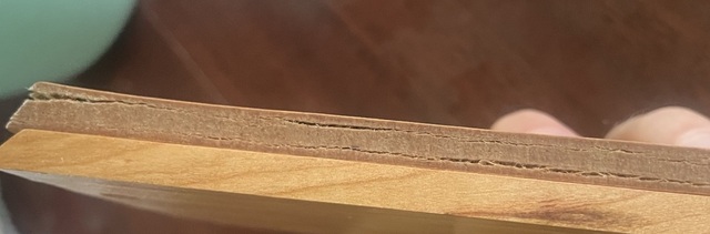 Cut-edge comparison — Supplier B Wall Dock (MDF core, top): swollen, fibrous, delaminating along the machined edge. Supplier A Wall Dock (solid cherry, bottom): intact, with only localized darkening near the edge.
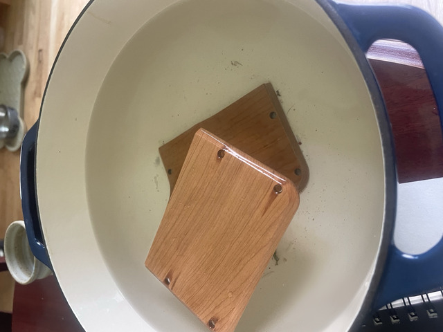 Wall Dock specimens during cold-water immersion; the drilled bulkhead holes are visible.
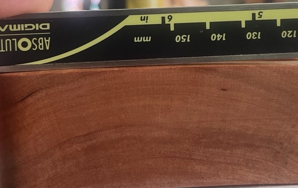 Base measured edge-on after soak — slight cupping along the bottom face.
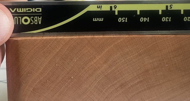 Base block gauged against the scale (end grain visible).
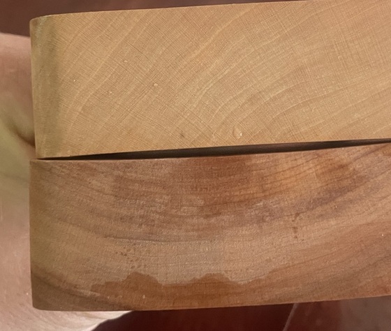 Two cherry Base blocks after soak — the lower (Supplier B, Danish oil) shows pronounced cupping and a moisture tide-line; the upper (Supplier A, Milesi XGC065) stayed flatter.
Appendix A — Soak-Test Measurements¶
Cold-water immersion. All values in inches; bold = final reading (36 h), with swell vs dry. Supplier A = solid cherry (Milesi XGC065). Supplier B = MDF-core veneer on the Wall Dock, Danish-oil cherry on the Base. A dried† = Supplier A specimens re-measured after ~2 weeks of air-drying at room conditions (logged 2026-06-21); percent shown vs A dry.
Wall Dock
| Dimension | A dry | 3 h | 15 h | 36 h | A dried† | B dry | 3 h | 15 h | 36 h |
|---|---|---|---|---|---|---|---|---|---|
| Length | 5.410 | 5.415 | 5.4195 | 5.420 (+0.2%) | 5.416 (+0.1%) | 5.381 | 5.381 | 5.392 | 5.394 (+0.2%) |
| Width | 3.719 | 3.730 | 3.750 | 3.779 (+1.6%) | 3.757 (+1.0%) | 3.682 | 3.684 | 3.708 | 3.720 (+1.0%) |
| Thickness | 0.258 | 0.265 | 0.276 | 0.280 (+8.5%) | 0.262 (+1.6%) | 0.195 | 0.200 | 0.269 | 0.295 (+51%) |
Supplier B's Wall Dock measured 0.195" as supplied — 55 mil under the 0.250" spec (the ~5 mm engineered-panel thickness). Its thickness was also gauged at the swollen corners along the way — 0.245–0.260 (3 h), 0.285 (15 h) — with two corners delaminating by 3 h and worsening through 36 h; by 36 h the general thickness (0.295) exceeded the earlier worst-corner readings. Supplier A showed no delamination at any point.
Base — both solid cherry; Supplier A finished Milesi XGC065, Supplier B finished Danish oil.
| Dimension | A dry | 3 h | 15 h | 36 h | A dried† | B dry | 3 h | 15 h | 36 h |
|---|---|---|---|---|---|---|---|---|---|
| Length | 5.927 | 5.935 | 5.9375 | 5.931 (+0.1%) | 5.933 (+0.1%) | 5.920 | 5.927 | 5.928 | 5.931 (+0.2%) |
| Width | 4.011 | 4.012 | 4.017 | 4.031 (+0.5%) | 4.036 (+0.6%) | 4.018 | 4.068 | 4.132 | 4.192 (+4.3%) |
| Thickness | 1.287 | 1.292 | 1.295 | 1.296 (+0.7%) | 1.284 (−0.2%) | 1.307 | 1.312 | 1.324 | 1.330 (+1.8%) |
| Warp | tiny | — | some | noticeable | — | tiny | — | heavy | severe |