Physical Installation
The XREG-010 is housed in a two-piece cherry hardwood enclosure. The "Wall Dock" screws to a wall or bulkhead.
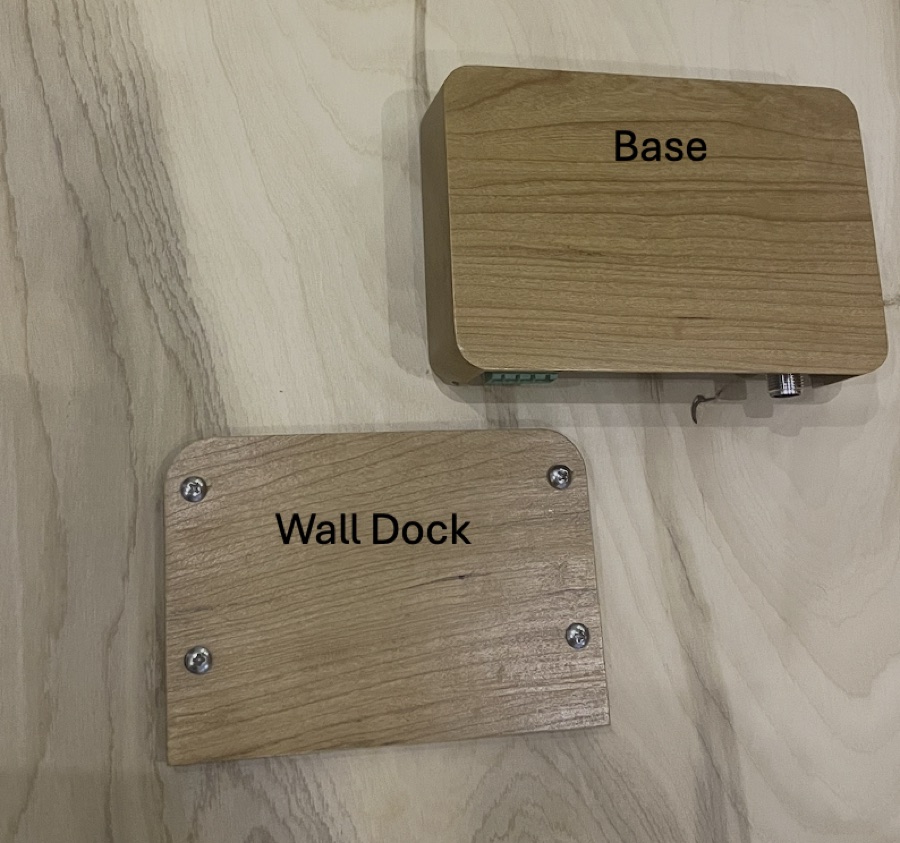
Then the Base slides straight down onto it and is retained by joint geometry and gravity.
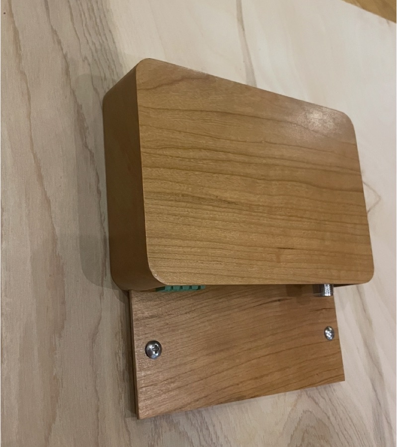
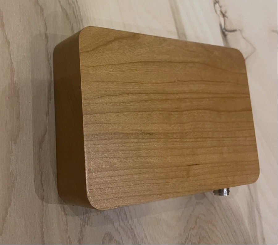
Position the bulkhead screw holes using the PDF file below.
Mounting location. Mount the regulator in a dry, ventilated space, at least 20 cm (8 in) from anywhere a person regularly sits or sleeps, and as close as possible to the battery bank. Within 3 to 6 feet is preferred, as it reduces voltage drop and maximizes accuracy of sensitive measurements. The regulator is not ignition protected. On a vessel with a gasoline engine, gasoline generator, or gasoline fuel tank, mount it outside the compartments containing them. Coast Guard rules (33 CFR 183.410) require electrical components in those spaces to be ignition protected or isolated from the fuel source.
Download: Mounting Instructions & Drilling Template (PDF)
Print at 100% scale ("Actual Size").
Before marking any holes, measure the printed template with a caliper or an accurate ruler: hole center-to-center spacing must be 4.742 in (120.4 mm) horizontally and 2.049 in (52.0 mm) vertically. If either is off, fix and re-print.
The template's punch marks are intentionally offset a small distance from the Wall Dock's hole centers. The dock is machined dry and expands from humidity in marine service, so the marks are biased to leave extra clearance on the side the wood will grow into.
Removing and re-installing the circuit board
The board ships already mounted to the Base with three screws, each with a plastic washer under the head. In most cases there is no reason to remove it, but if you must, be aware that the three screw holes are not all the same.
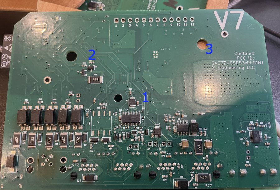
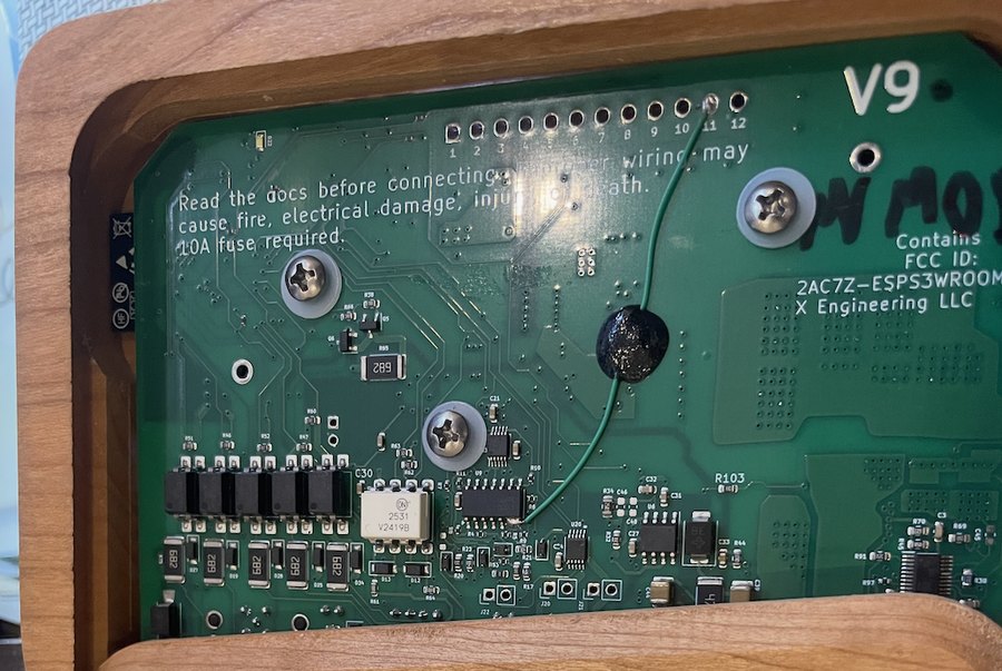
They differ for the same reason — expected moisture absorption compensation. Only hole 1 locates the board. Holes 2 and 3 are oversized so the wood can slide relative to the fiberglass PCB.
To re-install: tighten all three screws as you would any circuit-board screw — snug, board held firmly, not enough to crack anything. The plastic washers will allow the required sliding under any reasonable torque.