Control Switches
None of these switches are required. Fit the ones you want and cap the wires you don't need, as described on Data Cables & Pinout.
Switch Recommendations
| Photo | Switch | Use it for | |
|---|---|---|---|
| Default | 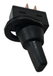 |
Sherco K3WP — splashproof SPST ON/OFF toggle with a detachable waterproof boot, 15 mm mounting hole | Every function, on a protected panel |
| Sealed | 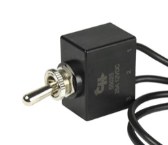 |
BEP 1002010 / Cole Hersee 55025 — sealed SPST OFF/ON with double O-ring, epoxy-sealed back and 10" of 14 AWG flying leads | A switch mounted somewhere it will get wet |
The K3WP is splashproof, not immersion-rated. For a switch that takes spray directly or sits in a locker that sweats, use the BEP. Its leads are 14 AWG, so splice them to your run with an HSBBS-10 16–14 AWG adhesive butt connector.
The two wiring patterns
Cable 3 — active-high. Pins 3, 5 and 7 are triggered by applying a voltage. Pin 2 on the same cable is a 5 V source: run it to the common side of the switches, and each switch's other side to its input pin. Anything from 5 V to 62 V works, so an existing switched 12 V circuit is also fine.
Cable 3 pin 2 (5 V) ──┬── switch ── Cable 3 pin 3  (OPT GPIO1)
                      ├── switch ── Cable 3 pin 5  (HIGH/LOW)
                      └── switch ── Cable 3 pin 7  (FORCEFLOAT)
Cable 4 — active-low. Pins 9 to 14 are triggered by grounding them. Pin 16 on the same cable is the ground return: run it to a common point near the switches and take every switch's return from there.
Cable 4 pin 9  (FactoryReset)  ── switch ──┐
Cable 4 pin 10 (WakeFromSleep) ── switch ──┤
Cable 4 pin 11 (WifiReset)     ── switch ──┼── Cable 4 pin 16 (GND)
Cable 4 pin 12 (AP/ClientMode) ── switch ──┤
Cable 4 pin 13 (RESET)         ── switch ──┤
Cable 4 pin 14 (ON/OFF)        ── switch ──┘
Pins 9, 11 and 12 are read once as the regulator starts, so set the switch first and then restart the regulator (pin 13 does that). Starting with pin 11 grounded opens the WiFi setup page and keeps the alternator off until the regulator is restarted with that switch open.
Charge rate and Maintain mode — the Physical Panel Override
Two of the Cable 3 inputs duplicate a dashboard control:
| Cable 3 pin | Switch on | Switch off | Same as the dashboard control |
|---|---|---|---|
| 5 (HIGH/LOW) | High charge rate | Low charge rate | Setup → Alternator → RPM Table → Charge Rate |
| 7 (FORCEFLOAT) | Maintain mode engaged | Maintain mode off | Setup → Battery → Charge Settings → Phase Definitions → Float Phase → Force "Maintain Mode" |
Which of the two sources controls the regulator is a single software setting, Physical Panel Override, under Setup → System → Security & Maintenance. It ships off. Either way, Maintain mode needs a battery shunt and stays off while CV Mode is on.
Pin 3 (OPT GPIO1) is a spare. It is isolated and wired through to the processor, but no function is assigned to it.
Terminating to the switch
The Cat6 conductor is 24 AWG and switch blades are sized for boat wire, so step up here:
- HSWSD-10 crimped straight onto 18 AWG tinned marine wire.
- HSBFN-10 fully insulated female quick disconnect at the switch's 0.250" blade. Its barrel is sized 16–14 AWG, so fold the 18 AWG conductor back on itself before crimping — doubled 18 AWG is about 3,250 circular mils, which sits between 16 AWG (2,580) and 14 AWG (4,110) and fills the barrel properly.
If the boat is standardized on 16 AWG, add an HSRSD-10 between the two steps.
Crimp first, then heat until the adhesive flows out of both ends of the sleeve, and pull-test every splice. Put a little dielectric grease on the blade before pushing the disconnect on.
ON/OFF
Cable 4 pin 14 shuts off the alternator field in hardware. Grounding that wire kills the field whether or not the firmware is running and whether or not the dashboard is reachable. This is a direct hardware toggle that works even with a malfunctioning processor, so it makes a good emergency stop for the alternator field.
Next step
Pin-by-pin colors and the rest of the terminations: Data Cables & Pinout.