Temperature Sensors
The regulator supports two alternator temperature sensor types, with a third theoretically possible:
| Option | Recommendation | Interface |
|---|---|---|
| Digital sensor (DS18B20) — included | Recommended | Dedicated digital (1-Wire) input on Cable 2 |
| 10 kΩ NTC thermistor | Supported, not recommended | Analog Channel 3 (AIN3) |
| Analog IC sensor (TMP235) | Theoretically possible, untested | Analog Channel 3 (AIN3) |
Installation of the included digital sensor is covered in Installation → Sensors → Temperature Sensor. This page is the deep dive on the options themselves.
Digital sensor (DS18B20) — recommended
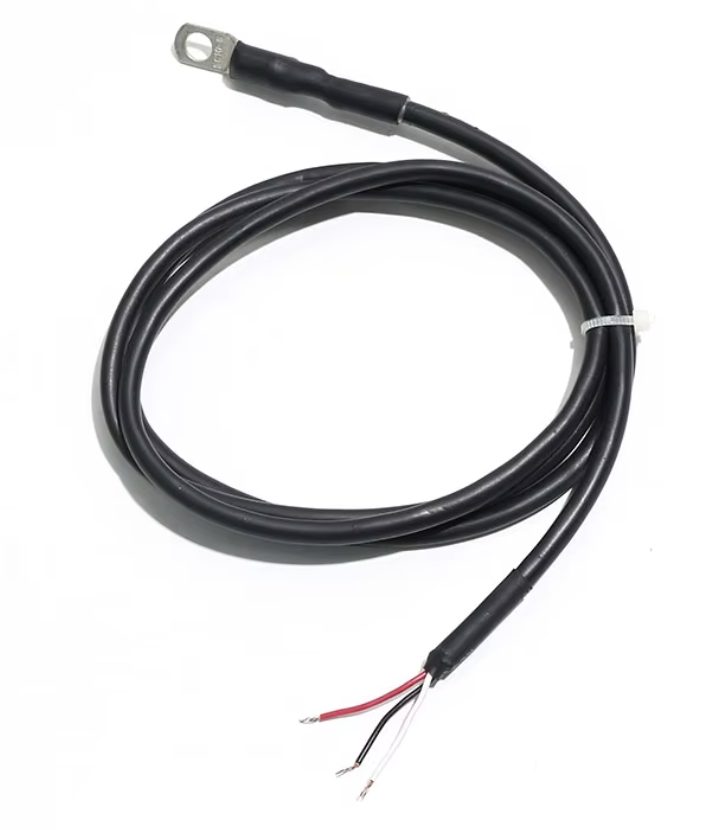
Three are supplied with the regulator, factory-sealed into copper ring lugs (M4, M5, and M8 hole sizes) on 0.5 m leads.
This is the sensor everyone should use, for three reasons:
- The reading is digital data, not an analog level. Lead resistance, connector corrosion, and electrical noise cannot shift the temperature value. A corrupted transmission fails its integrity check (CRC) and is discarded rather than silently read wrong — important in the electrically hostile environment next to an alternator.
- Factory calibrated. ±0.5 °C typical accuracy across the alternator operating range, with no user calibration constants to enter.
- The board input is noise-hardened for the alternator environment, with a series resistor and filter capacitor on the data line — full circuit details, designators, and PCB revision notes in the interface circuit section below.
10 kΩ NTC thermistor — supported, not recommended
Analog Channel 3 (AIN3) accepts a standard 10 kΩ NTC thermistor wired against a 10 kΩ divider resistor on the board.
Why it's not recommended: the divider output crowds the 3.3 V rail above roughly 90–100 °C — exactly the band that matters for alternator protection. Resolution and accuracy collapse where you need them most: expect ±2–3 °C near 100 °C, degrading to ±3–5 °C at 125 °C, versus ±0.5 °C from the digital sensor everywhere. The full voltage table, accuracy budget, and disconnect-detection behavior are in Analog Inputs → Channel 3.
To use one anyway:
- Remove the 0 Ω ground jumper on the board — Channel 3 ships shorted to ground as a spare ground pin. See Analog Inputs for the designator.
- Wire the thermistor between 3.3 V and AIN3. The 3.3 V supply is the Orange/White wire on Cable 2 — the same wire that powers the digital temperature sensor. AIN3 is available on both Cable 2 (Green) and Cable 1 (Blue); pin assignments in Data Cables & Pinout.
- In the dashboard temperature settings, enter the constants for your part: Thermistor Beta (from the thermistor datasheet — 3380 for the reference Murata NXFT15XH103FA2B050), Thermistor Series Resistor (10 kΩ as built), and Thermistor Reference Temp (25 °C for nearly all parts).
- Flip the Temp Source toggle from Digital to Thermistor.
Use 3.3 V excitation, not 5 V
A 5 V supply pin also exists on Cable 1, but the firmware's thermistor conversion assumes 3.3 V excitation. Powering the divider from 5 V produces readings that are wrong everywhere except by coincidence, and pushes the divider output above the ADC's usable range at high temperature. Use the 3.3 V wire.
Other thermistor values
Any 10 kΩ NTC works with a settings change only — Beta values vary widely between vendors (3380, 3435, 3950, 4250 are all common), and the firmware accepts whatever the datasheet says.
Thermistors of other resistances (2 kΩ, 5 kΩ, 100 kΩ, etc.) are theoretically usable with one board change: replace the 10 kΩ divider resistor (the 0603 pulldown on Channel 3 — designator in Analog Inputs) with a value near the thermistor's 25 °C resistance, then set Thermistor Series Resistor to the installed value. Resolution is best when the fixed resistor roughly matches the thermistor's resistance in the temperature band you care about.
Analog IC sensor (TMP235) — theoretical, untested
A TI TMP235 temperature sensor IC uses the same circuit as the thermistor, unmodified. Power it from the same 3.3 V wire, tie its output to the same AIN3 node, and the existing 10 kΩ resistor — the divider bottom in the thermistor case — simply becomes a light load on the TMP235's low-impedance output. No board changes either way.
Its output is a linear voltage — 10 mV/°C with 0.5 V at 0 °C — which stays well-centered in the ADC range all the way past +140 °C, avoiding the thermistor's high-temperature compression entirely.
The caveat: current firmware converts Channel 3 through the thermistor equation (Beta model), so the TMP235's linear output would read as nonsense without a firmware change to add a linear conversion mode. The hardware path is sound on paper; nobody has run one in the field. If you want to try it, get in touch.
Accuracy and range comparison
All three options compared at the temperatures that matter. Thermistor figures assume the reference Murata part with correct settings entered; full derivation in Analog Inputs → Channel 3.
| Digital (DS18B20) | 10 kΩ NTC thermistor | TMP235 (A4 grade) | |
|---|---|---|---|
| Sensing range | −55 to +125 °C | −40 to +125 °C (rails out ~+135 °C) | −40 to +150 °C |
| Accuracy, −10 to +85 °C | ±0.5 °C (datasheet max) | ±1 to 2 °C | ±1 °C typical |
| Accuracy at 100 °C | ±2 °C max bound (typically much better) | ±2–3 °C | ±1 °C typical |
| Accuracy at 125 °C | ±2 °C max bound | ±3–5 °C | ±1 °C typical |
| Signal at high temp | Digital — unaffected | Crowds the 3.3 V rail; resolution collapses above ~100 °C | Linear everywhere — 1.5 V at 100 °C, far from the rail |
| Corrupted-reading behavior | Fails checksum (CRC), discarded | Reads wrong silently | Reads wrong silently |
| Lead resistance / corrosion effect | None | Adds directly to apparent thermistor resistance | Negligible (low-impedance output) |
| Disconnect detection | No response on the data line | Node pulled to 0 V — below the 0.05 V "no sensor" floor | Same — node pulled to 0 V, detected (lowest real reading is 0.100 V at −40 °C) |
| Firmware support | Yes (default) | Yes (Temp Source → Thermistor) | Not yet — needs a linear conversion mode |
TMP235 accuracy figures are for the A4 grade (the part documented in Analog Inputs); its worst-case datasheet bound is ±2.5 °C anywhere in −40 to +150 °C, with no extra penalty at high temperature. An A2 grade (±0.5 °C typical) also exists.
The shape of the problem: an alternator protection sensor earns its keep between roughly 90 and 125 °C. The thermistor is weakest exactly there — its divider output flattens against the supply rail, so each ADC step spans more degrees and part tolerances dominate. The chart below makes it visible: in the shaded protection band the thermistor curve has gone nearly flat while the TMP235 line keeps its full 10 mV/°C slope.

The DS18B20's accuracy bound also widens above 85 °C (the ±2 °C figure is the datasheet worst case), but its reading stays trustworthy: it cannot drift with wiring condition and cannot be silently corrupted by noise. The TMP235 would be the best analog performer at high temperature, which is why it is documented here despite being untested.
Output voltage by temperature (3.3 V excitation)
Computed from the Beta model (R25 = 10 kΩ, β = 3380 K) against the 10 kΩ divider resistor, and the TMP235 transfer function (0.500 V at 0 °C, 10 mV/°C):
| Temp (°C) | R_NTC (Ω) | NTC node (V) | TMP235 node (V) |
|---|---|---|---|
| −40 | 235,831 | 0.134 | 0.100 |
| −20 | 75,022 | 0.388 | 0.300 |
| 0 | 28,224 | 0.863 | 0.500 |
| 15 | 14,820 | 1.330 | 0.650 |
| 25 | 10,000 | 1.650 | 0.750 |
| 50 | 4,160 | 2.330 | 1.000 |
| 75 | 1,963 | 2.759 | 1.250 |
| 100 | 1,024 | 2.993 | 1.500 |
| 125 | 580 | 3.119 | 1.750 |
| 140 | 426 | 3.165 | 1.900 |
Between 100 and 125 °C the NTC node moves 126 mV total (about 5 mV/°C and shrinking); the TMP235 moves 250 mV at a constant 10 mV/°C. ADC quantization is never the limit on this channel — sensor and resistor tolerances are — but the flattening NTC curve multiplies those tolerances into degrees.
Supply load is negligible for all three: the thermistor divider draws about 0.17 mA at 25 °C rising to about 0.31 mA at 125 °C; the TMP235 draws about 9 µA quiescent plus under 0.2 mA into the 10 kΩ load; the DS18B20 draws about 1 mA peak during conversion.
DS18B20 interface circuit
The DS18B20 connects to an ESP32 GPIO over the 1-Wire protocol, in normal powered mode (not parasite mode) with a standard 1-Wire pull-up resistor. The design includes optional noise-hardening components for electrically noisy environments such as engines and alternator systems. The sensor connects through Cable 2 pin 3 (Green/White wire, TEMP-DQ).
Circuit topology (design intent)
3.3 V → 4.7 kΩ pull-up → DATA node → ESP32 GPIO DATA node → 100 Ω series resistor → DS18B20 DQ pin DATA node → 1 nF capacitor → GND
The capacitor is intended to sit on the MCU side of the series resistor — between the DATA node (GPIO pin side) and GND — so that it filters noise before it reaches the ESP32.
Designators (V9 build)
| Element | Designator | Value | Footprint |
|---|---|---|---|
| Pull-up to 3V3 | R77 | 4.7 kΩ | 2512 (oversized for hand-replaceability) |
| Series resistor (MCU to sensor node) | R1 | 100 Ω | 0603 |
| Noise filter cap (MCU side, to GND) | C49 | 1 nF | 0603 |
PCB revision notes
Rev 7 and Rev 8 — cap pad on wrong side. On Rev 7 and Rev 8 PCBs, the 1 nF capacitor footprint was accidentally placed on the sensor side of the 100 Ω resistor rather than the MCU side. The actual circuit on those boards:
3.3 V → 4.7 kΩ pull-up → DATA node → ESP32 GPIO DATA node → 100 Ω series resistor → sensor node → DS18B20 DQ pin sensor node → 1 nF capacitor → GND ← wrong side
Effect: the RC filter still attenuates noise arriving from the sensor wire (the dominant noise path in an alternator environment), so the cap provides partial benefit even in this position. However, it does not filter noise that couples onto the PCB trace between the GPIO pin and the resistor. Field workaround on Rev 7/8: the cap can be left installed — it still helps. If communication errors increase, remove it (see troubleshooting below); the pad is accessible and the cap can be physically removed with a soldering iron.
V9 — fix applied. V9 has the cap on the correct (MCU) side of the series resistor. Per netlist audit 2026-05-23: C49 (1 nF) sits between the ESP32 GPIO13 net and GND, and R1 (100 Ω) sits between that node and the off-board sensor wire. This matches the original design intent and gives full noise rejection both for radiated pickup on the sensor cable and for any RFI that couples onto the MCU-side PCB trace.
Component roles
Pull-up resistor (4.7 kΩ) — required by the 1-Wire protocol: both the ESP32 and DS18B20 use open-drain signaling, so when neither device pulls the line low, the pull-up restores it to 3.3 V. It is intentionally a large 2512 package so it can be hand-replaced with a soldering iron, without specialized rework tools.
Series resistor (100 Ω) — limits fault current if the MCU pin is misconfigured, provides mild signal damping, and improves ESD robustness on the data line. Not required for normal DS18B20 operation, but adds robustness.
Noise filter capacitor (1 nF) — filters high-frequency electrical noise and suppresses spikes on long wires. It forms a small RC filter with the 100 Ω resistor: τ = 100 Ω × 1 nF ≈ 100 ns, much shorter than typical 1-Wire timing windows, so it normally does not affect communication.
Troubleshooting
If communication problems occur, remove the optional filtering components in this order:
- Remove the 1 nF capacitor
- Remove the 100 Ω series resistor
The minimal canonical circuit for DS18B20 operation is: 3.3 V → 4.7 kΩ → DATA → ESP32 + DS18B20.
Note for Rev 7/8: on these boards the cap pad is on the sensor side of the resistor (see PCB revision notes above). Removing the cap is still the correct first step.
The circuit assumes short PCB traces or moderate cable length; very long cables may require pull-up tuning.
Selecting the temperature source
The Temp Source toggle in the dashboard temperature settings selects Digital or Thermistor. All thermal protections — temperature alarms, thermal current derating — act on whichever source is selected.