Initial Settings
After Connecting to the Regulator you have the dashboard open in a browser or in the app. This page walks the whole first-boot sequence the way you will experience it: one required form, then a short guided chain of screens that ends by handing you to Automatic System Characterization, then a pass through the remaining Setup tabs. Plan on 15–30 minutes plus a characterization run. Leave the engine off until 4f. Tachometer Calibration asks you to start it: the field resistance test right after the Prerequisites screen runs with the engine stopped.
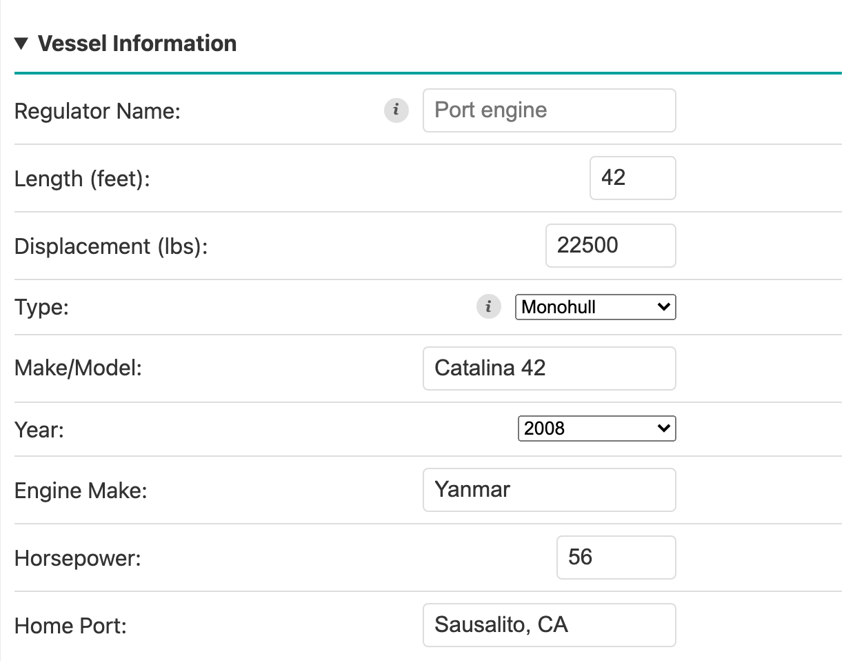
The screenshots below come from an example installation, a 42-foot monohull with a 400 Ah 12 V LiFePO4 bank and an 80 A alternator. Your values will differ; the screens will not.
1. What you see on arrival
The permanent header is always at the top: live voltage, state of charge, alternator and battery current, temperatures, RPM, charging-system health, and the master Alternator Enable toggle. The dot at the far left is teal whenever live data is arriving (see The connection dot).
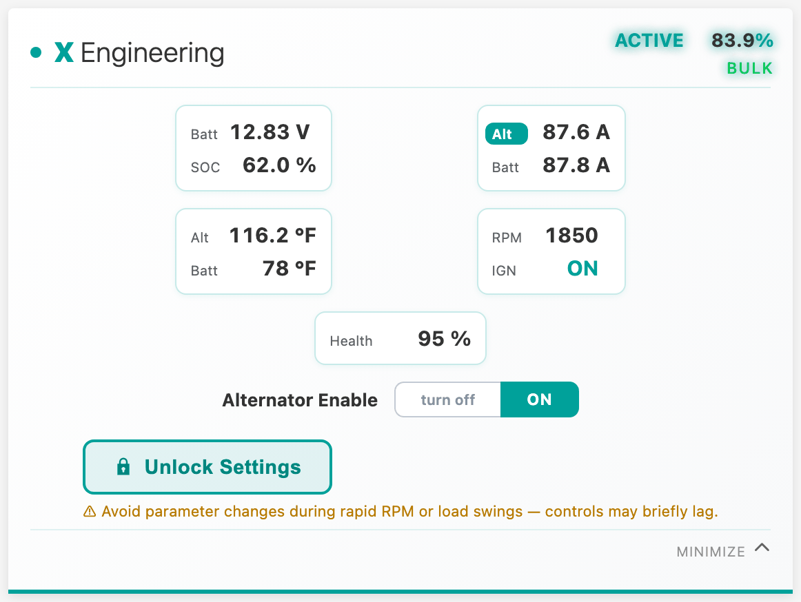
Everything is readable while locked: you can watch every gauge and plot without unlocking anything. Two things are special about a brand-new device:
- Settings are locked. The Unlock Settings padlock button at the bottom of the header is the only locked-state indication there is.
- You land on Setup → Vessel Info, and every tab outside Setup stays blocked until Vessel Info is saved. The cloud features (forecasts, leaderboards, charging analytics) need to know your boat and battery to be useful, so this form comes first.
2. Unlock Settings
Click Unlock Settings. By default there is no password: anyone on the XREG-010's WiFi network is already trusted, so the button is an acknowledgment ("I'm about to change settings"), not a login. On a shared network such as marina WiFi, add one under Setup → System → Settings Password. Unlocking opens a window on the device itself during which settings changes are accepted from any connected device, or only from the one that typed the password if one is set. The window has no time limit. When you press Lock Settings (Setup → System), when another connected device locks it, or when the regulator reboots, the device locks again and rejects every settings change until the next unlock. Turning the alternator off never requires unlocking. (With the header minimized, the button becomes a small Unlock chip inside the collapsed strip, so a locked-and-minimized session is never a dead end.)
3. Setup → Vessel Info (required)
Three sections. Fill in all of them.
Vessel Information covers the boat itself:
Charging Equipment covers the electrical system:
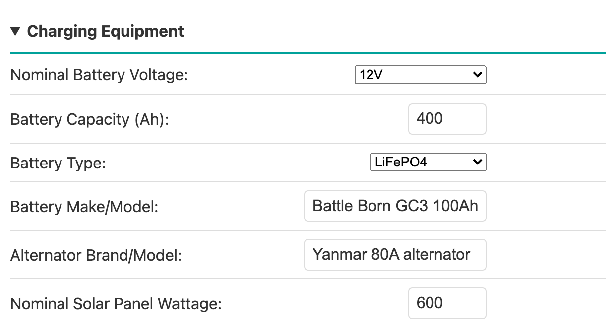
Nominal Battery Voltage deserves care. It is the sole source of the system voltage class (12 / 24 / 36 / 48 V), and changing it later rescales the charge profile, the over-voltage margins, the duty limits and the hard-shutdown voltage to the new class, and the dashboard warns you before applying. A later class change also wipes the learned tachometer keep-alive floor table back to its flat default, because floors learned against the old limits can sit above the new ones, and you would have to re-run that commissioning step. Set the class correctly here rather than relying on a later change.
Physical Regulator Installation records how the device is mounted:
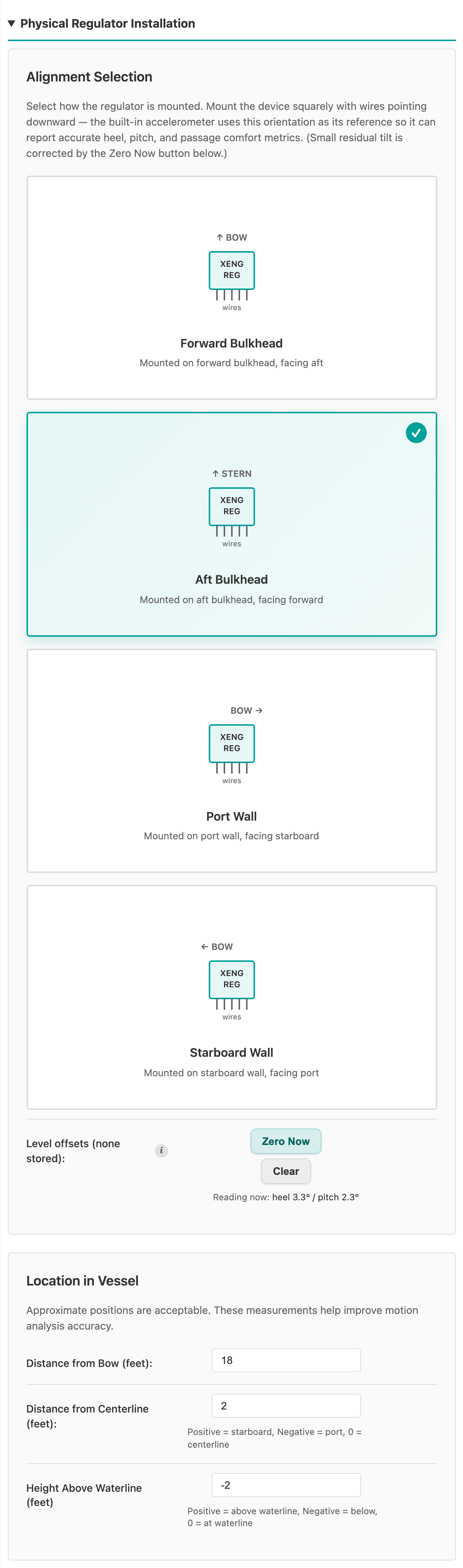
Pick the card matching your mounting orientation. The built-in accelerometer (IMU) uses it as its reference for heel, pitch, and passage-comfort metrics. With the boat sitting level, press Zero Now to capture the small residual tilt. It is stored as the Level offsets shown on that row, and heel and pitch then read zero at that attitude. Take it with the boat at rest, because whatever tilt the device is in at that moment is baked in until you zero it again. The position-in-vessel fields feed the motion analysis, and approximate positions are fine.
Click Save.
4. The guided chain after Save
On a first save the app does not drop you back into the tabs. It walks you through a short chain of screens that ends at characterization. Each screen can be skipped; anything you skip stays editable later under Setup.
4a. Commissioning Prerequisites
This screen prepares the necessary settings before system characterization. On a phone it opens with a reminder to use a laptop or tablet if you can. Setup and Commissioning works on a phone, but it's a worse UX on a small screen.
Digital Temperature Sensors. Every sensor on the 1-Wire bus, with its live reading. Set what each one measures: Alternator, Battery, Extra, or Not used. To tell them apart, warm one by hand and watch which row rises. Rescan re-reads the bus if you plug one in while the screen is open. A sensor that has left the bus reads not found; one still listed but no longer answering reads not responding. The Alternator assignment is the only one that blocks Next, because that sensor is what the over-temperature protection acts on, and commissioning is what drives the alternator hard.
Alternator. The Alternator Temperature Source (Digital, meaning the sensor supplied with the kit, or Thermistor with its three constants) and the Alternator Temperature Limit.
Then Field wiring: P-type or N-type, matching how the field is wired at the regulator (P-type, N-type). It tells the drive-heat protection which part to watch: the freewheel diode's heat spreader on P-type, the field connector on N-type. Next stays disabled, with the reason under it, until a wiring is chosen. It is also under Setup → Alternator → Basic → Output Control. The field resistance is measured by the regulator itself, on the screen after this one (Field resistance test, below).
Battery. Whether the battery shunt (INA228) is installed, its resistance, and its Shunt location: Negative lead or Positive lead, the battery cable the shunt sits in (P-type, N-type). With a shunt installed, Next stays disabled until the location is chosen. A read-only Battery temperature line names the measured source the regulator is reading, or says none is installed. It never blocks Next. The source itself is chosen later, under Setup → Battery → Charge Settings → Battery Temperature. A table of common shunt values is built in; Victron shunts are the 50 mV family. Without a shunt, state of charge, the battery-current limit, and zero-current float are unavailable, and absorption ends on its time limit instead of on tail current, so the shunt question is worth getting right first. A shunt the regulator reads only over NMEA 2000 or VE.Direct counts as None here. Set up under Setup → Integrations, it still lets absorption end on tail current.
Battery voltage for charge stage changes (Onboard, NMEA 2000, or Victron) decides when charging moves from bulk to absorption to float, and back to bulk. The control loops always use the onboard sensor. Choose an external source if the Regulator Ground Wire is longer than 6 ft or smaller than 12 AWG, or if a shunt in the negative lead is not wired to the regulator on Cable 2 pins 9 and 10.
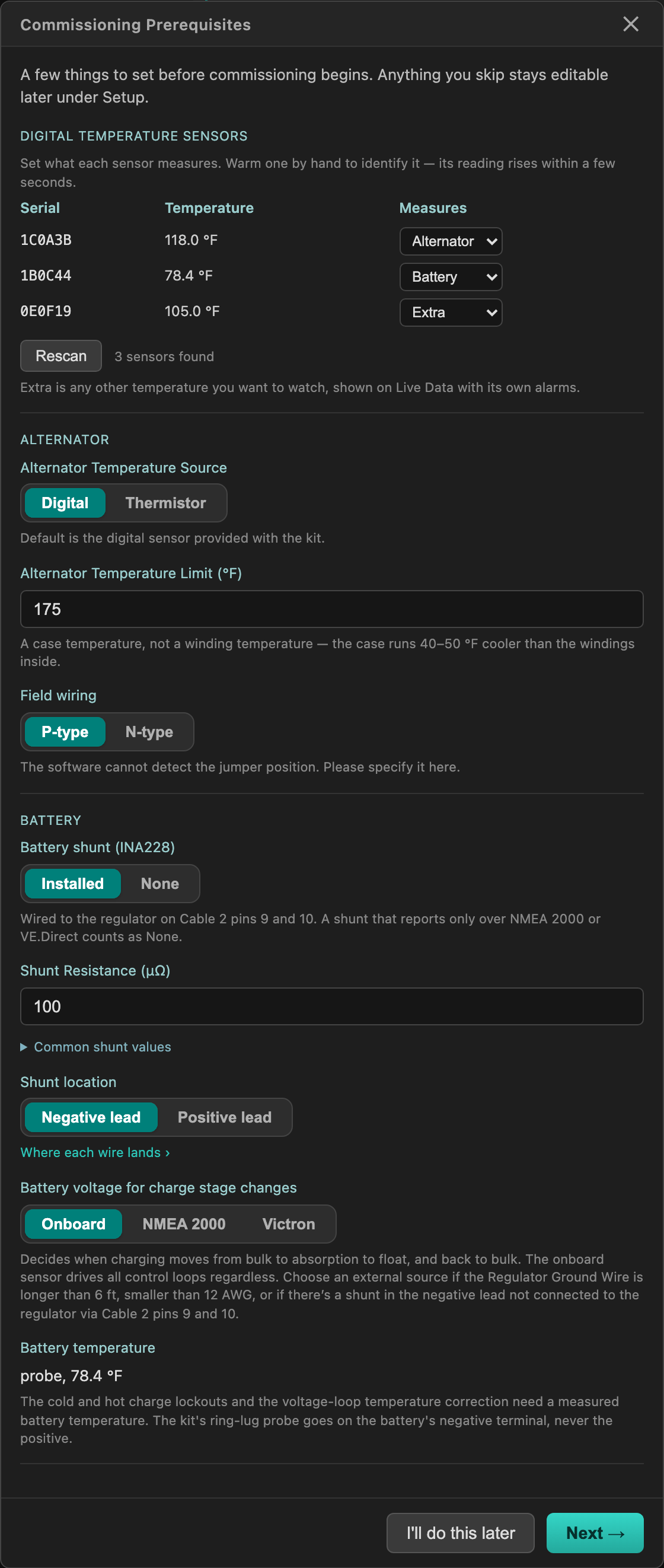
Battery temperature thresholds are not here. Recommend Initial Charging Settings in 4b proposes the cold-charge lockout switch from your chemistry (and, with a battery probe assigned, the hot-charge lockout and its Max Charge Temp); the cold floor, Min Charge Temp, keeps its shipped 40 °F (4 °C) until you edit it under Setup → Battery → Charge Settings → Battery Temperature. Assigning a sensor to Battery does belong here, and it is why this screen comes first: with a battery sensor assigned, the recommendations that follow include the battery-temperature gain derate and the hot-charge lockout, and commissioning stamps the measured battery temperature it fitted the voltage loop against. Commission with no measured source and there is no stamp to correct from, so the gain derate stays inert at a flat 1.0 until Voltage Control Autotuning is run again with one fitted.
The temperature limit is a case temperature, not a winding temperature. See the temperature settings section below for how to choose it.
Field resistance test
Next on the Prerequisites screen opens Field Resistance. The regulator needs the field circuit's resistance to estimate field current, and the field stays off until one is recorded, unless a 12 V system with no shunt skips the test (below). Leave the engine off, with the key on (or Ignition Override on) and Alternator Enable on, and follow the screen.
With a battery shunt wired to the regulator, the test runs by itself in about a minute. A shunt the regulator reads only over NMEA 2000 or VE.Direct does not count.
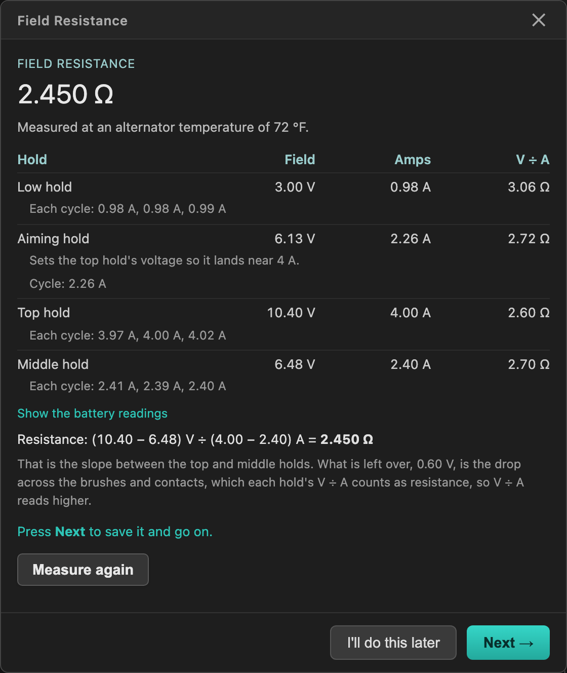
Without a shunt on a 24 V and up system, you read the field current on a DC clamp meter or a multimeter with a 10 A DC range while the regulator holds the field, then type each reading in and press Record. The screen draws both hookups: the clamp around the field wire, or the multimeter in place of the pulled field fuse. A multimeter needs solid connections on both leads, and a second person to help is preferred.
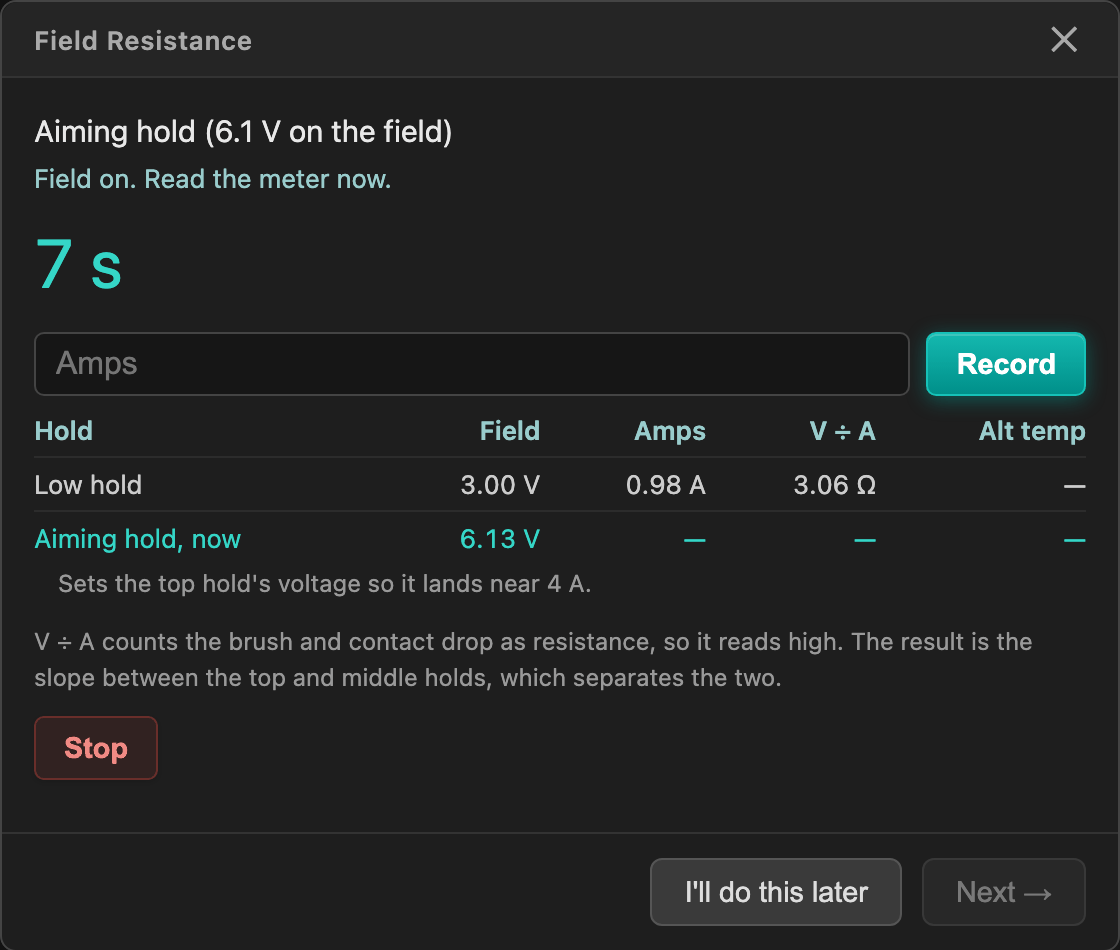
Without a shunt on a 12 V system, the test is optional: it only makes the Field Amps reading more accurate. The screen opens on Skip the test, which sets the field resistance to 2 Ω and moves on. At 12 V neither the 10 A field ceiling nor the drive-heat limit acts on that value. Test anyway opens the meter screen described above.
If the test fails, the screen says why and offers Try again.
To measure again later, for example after replacing the alternator, its brushes, or the field wiring, press Measure under Setup → Alternator → Basic → Output Control. That row also takes a result from an earlier test, typed in with the alternator temperature the test showed for it. Never type an ohmmeter reading there. A measured or typed value replaces the 2 Ω of a skipped test.
4b. Recommend Initial Charging Settings
The regulator works out a full set of chemistry-matched charge, protection, and alarm values from the bank you just described, and lists every one beside its current value. Rows that already agree are highlighted and marked matches, with nothing to apply. The rest arrive ticked: untick anything you want to keep, then press Apply Selected. Nothing is written to the device until you do.
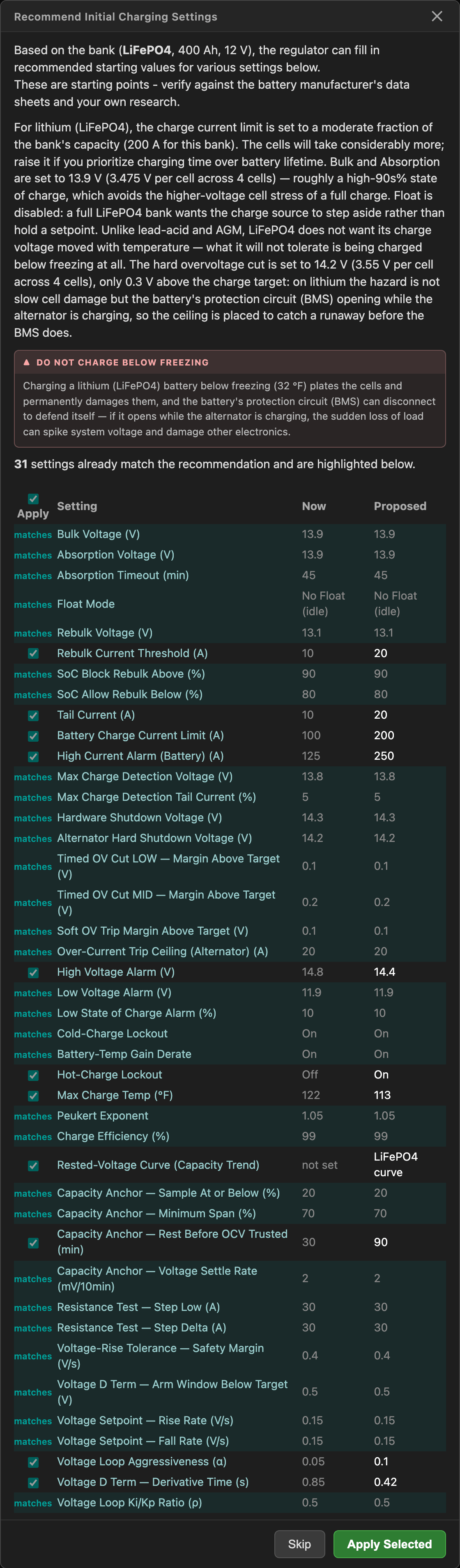
Every value here is a starting point, picked to be safe on a battery whose data sheet the regulator has never seen. Check each one against the charge voltages and current limits your battery manufacturer publishes, and change the ones where the manufacturer disagrees. Setting Battery Type to Other produces no proposal at all: you set every charge-stage and protection value by hand, and the Prerequisites screen in 4a collected the critical ones.
The proposals lean gentle for lithium. Bulk and absorption at 13.9 V on a 12 V bank is already a high-90s% state of charge, and holding a LiFePO4 bank higher buys very little capacity for a lot of extra cell stress, so Float Mode is proposed as No Float (idle). AGM and flooded banks get their conventional higher targets, flooded highest of the three, because the dominant killer of a flooded battery is undercharge rather than overcharge.
Five of the proposed values form the overvoltage ladder above the charge target, and they do different jobs. The soft shed, which Setup lists as the Group 2 trip margin above target, is the first line: crossing it trims charge current in proportion to how far over the bus is, continuously and without cutting anything, and most excursions end there with nothing felt at the engine. The timed cuts open the field, but only after the bus has held above their line for the full dwell, 400 ms for the LOW tier and 150 ms for the MID tier. One reading back under the line resets the clock, so a ripple crest that flirts with a line accumulates nothing.
The software instant cut and the hardware cut are absolute backstops with no dwell at all. The software one is logged, counted, and recovers on its own; the hardware one is the INA228 shunt monitor's alert pin pulling the field-enable line down with no firmware involved. The three lines above target are stored as margins, so they follow the target down into float, while the two backstops are fixed volts. All of them stay editable afterwards under Setup → Alternator → Protections → Detection, where the two timed cuts and the two absolute cuts share an Over-Voltage Ladder card in rung order.
What the tool proposes on a 12 V bank, in volts:
| Rung | LiFePO4 | AGM | Flooded |
|---|---|---|---|
| Bulk and absorption target | 13.90 | 14.40 | 14.60 |
| Soft shed | 14.00 | 14.90 | 15.10 |
| Timed cut LOW (400 ms) | 14.00 | 15.00 | 15.20 |
| Timed cut MID (150 ms) | 14.10 | 15.10 | 15.30 |
| Float target | none | 13.60 | 13.40 |
| Soft shed, in float | none | 14.10 | 13.90 |
| Timed cut LOW, in float | none | 14.20 | 14.00 |
| Timed cut MID, in float | none | 14.30 | 14.10 |
| Software instant cut (absolute) | 14.20 | 15.90 | 15.90 |
| Hardware cut, INA228 (absolute) | 14.30 | 16.00 | 16.00 |
The settings themselves hold the three margins rather than the lines: 0.10, 0.10, and 0.20 V for LiFePO4, and 0.50, 0.60, and 0.70 V for AGM and flooded. Bank capacity does not enter any of these voltages. It sets the current numbers instead, meaning the charge-current limit, the tail current, the rebulk current, and the absorption timeout.
Multiply the 12 V column by two for a 24 V bank and by three for a 36 V bank. Targets and rungs alike scale, because each of them is really a per-cell figure. The lithium target is 3.475 V per cell on any bank, which comes out as 13.9 V across four cells at 12 V and 55.6 V across sixteen at 48 V. The margins scale for a less obvious reason. A lithium battery's protection circuit (BMS) trips on its single highest cell, while the regulator only ever sees the pack total, so the margin has to cover however far apart the cells drift. One 50 mV outlier eats 0.15 V of pack-referred margin on a 4-cell 12 V bank and 0.75 V on a 16-cell 48 V bank, so the allowance for cell-to-cell spread genuinely grows with cell count.
The lead-acid and AGM hardware cut is the one rung that stops scaling, because it is an equipment rating and not a battery number. Lead-acid tolerates brief bounded excursions above its charge target, since every lead-acid damage mechanism accumulates over minutes to years, so that ceiling is placed where the boat's DC equipment becomes the limiting factor. Published continuous input ratings for marine DC gear top out near 16 V on a 12 V system, and 16 V of equipment rating stays 16 V of equipment rating on any bank, so the ceiling holds at 60 V on a 48 V system instead of reaching 64 V. The software cut follows it down, staying 0.1 V per 12 V of bank underneath, and the three target-relative lines are compressed by one common factor to fit below that, which is why the 48 V lead margins come out smaller than four times the 12 V ones. Check the ceiling against the lowest maximum input voltage of anything sharing the bus, and lower it if something is rated below it.
The 48 V proposal, in volts:
| Rung | LiFePO4 | AGM | Flooded |
|---|---|---|---|
| Bulk and absorption target | 55.60 | 57.60 | 58.40 |
| Soft shed | 56.00 | 58.89 | 59.11 |
| Timed cut LOW (400 ms) | 56.00 | 59.14 | 59.26 |
| Timed cut MID (150 ms) | 56.40 | 59.40 | 59.40 |
| Software instant cut (absolute) | 56.80 | 59.60 | 59.60 |
| Hardware cut, INA228 (absolute) | 57.20 | 60.00 | 60.00 |
The reasoning behind the dwell times, and how to place the two absolute rungs against a specific battery's published BMS disconnect voltage, is on Protection Timing.
The setup chain offers this screen when the battery on file is new or has changed. The same list is available at any time from Setup → System → Recommend Initial Charging Settings, so skipping it here costs nothing and you can come back to it after reading the data sheet. On a later visit the two values that characterization measures for itself (the alternator over-current trip ceiling and the voltage-rise tolerance safety margin) arrive unticked, so re-applying the chemistry recommendations cannot overwrite a measurement unless you tick them.
4c. State of charge starting estimate
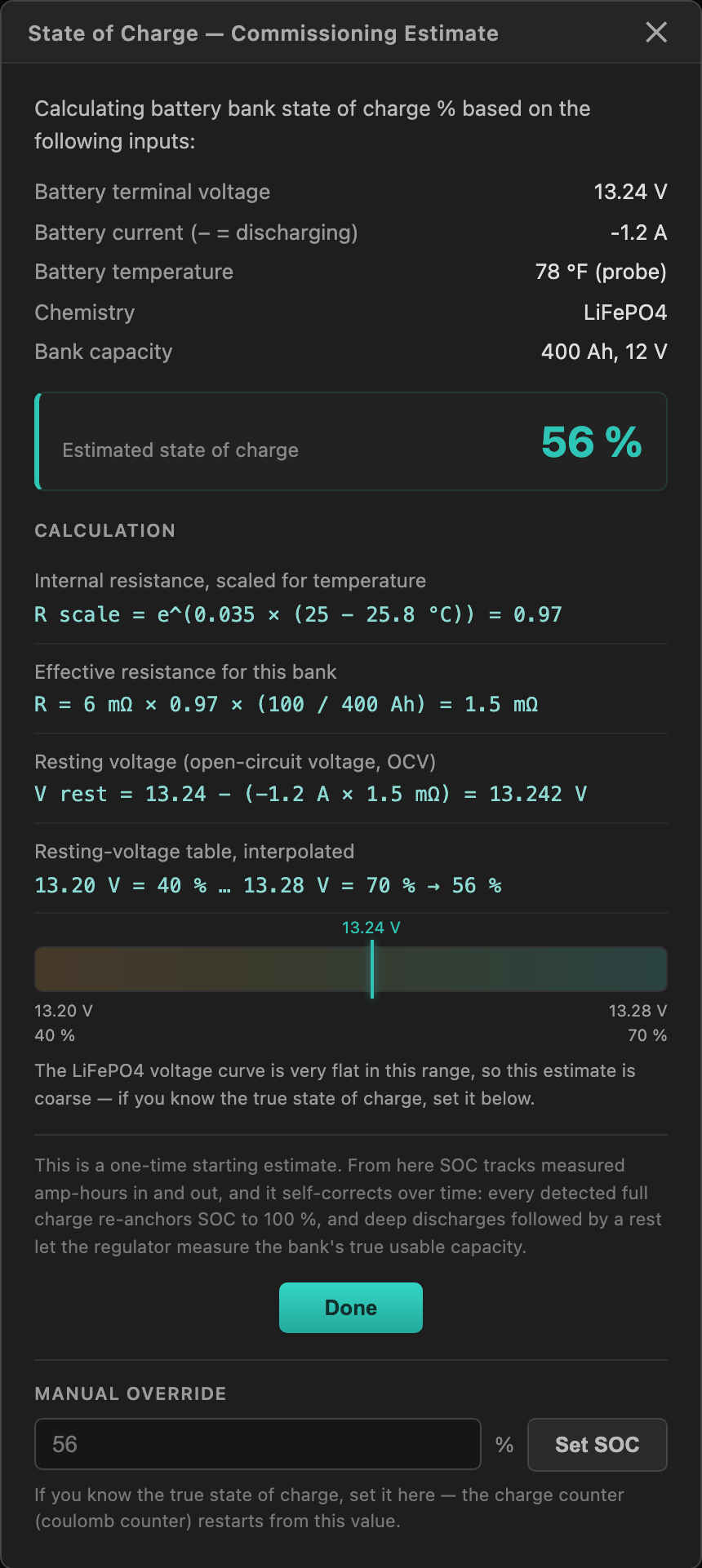
The regulator estimates state of charge from resting voltage and shows its work. Voltage-based estimates on LiFePO4 are coarse across the flat middle of the curve. If you know the true state of charge, type it in and press Set SOC. Don't agonize: the first detected full charge re-anchors the counter to 100 % and it is self-correcting from there.
4d. Automatic maintenance restarts
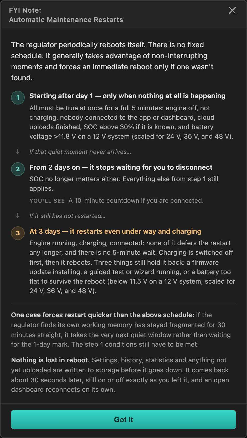
A one-time notice: the regulator periodically reboots itself for housekeeping, and it explains the escalation schedule it uses to find a harmless moment. Nothing is lost across these restarts. Read it and press Got it.
4e. Charge Rate Limits
The maximum alternator current at each of 10 engine speeds, in two independent tables: High is your system's full capability; Low is a gentler everyday rate (a third of High is a good start). Between the speeds you enter the limit follows a straight line; below the first and above the last it holds flat. The Continue button you pick sets which table is active, and characterization runs against it. Continue in Low keeps the tests gentle on the alternator and battery; switch to High once commissioning is done.
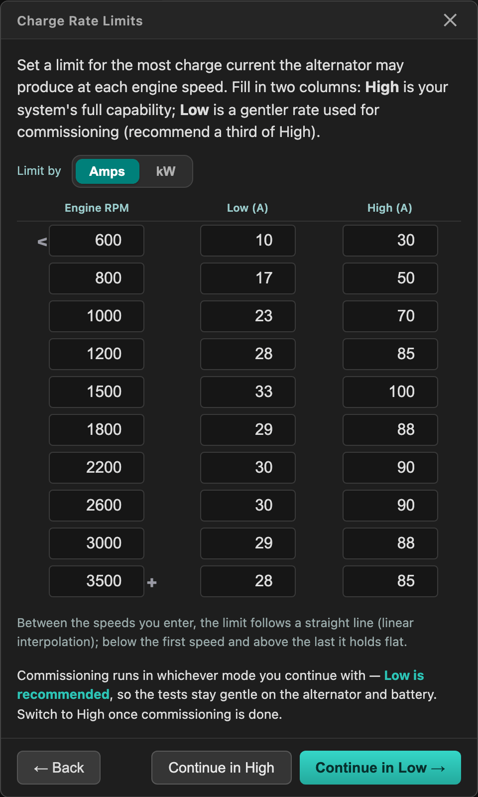
Start conservative. Raise the numbers once you have confirmed the alternator sustains them at each speed without overheating; the per-RPM overheat counters on the RPM Table tab (below) tell you exactly that over time.
4f. Tachometer Calibration
Start the engine (idle is fine, since no field is driven here). Enter the pulley ratio: crankshaft pulley diameter divided by alternator pulley diameter. A ruler estimate is fine. Then adjust the scaling-factor slider until the live reading matches your tachometer. Extreme precision is not needed for either.
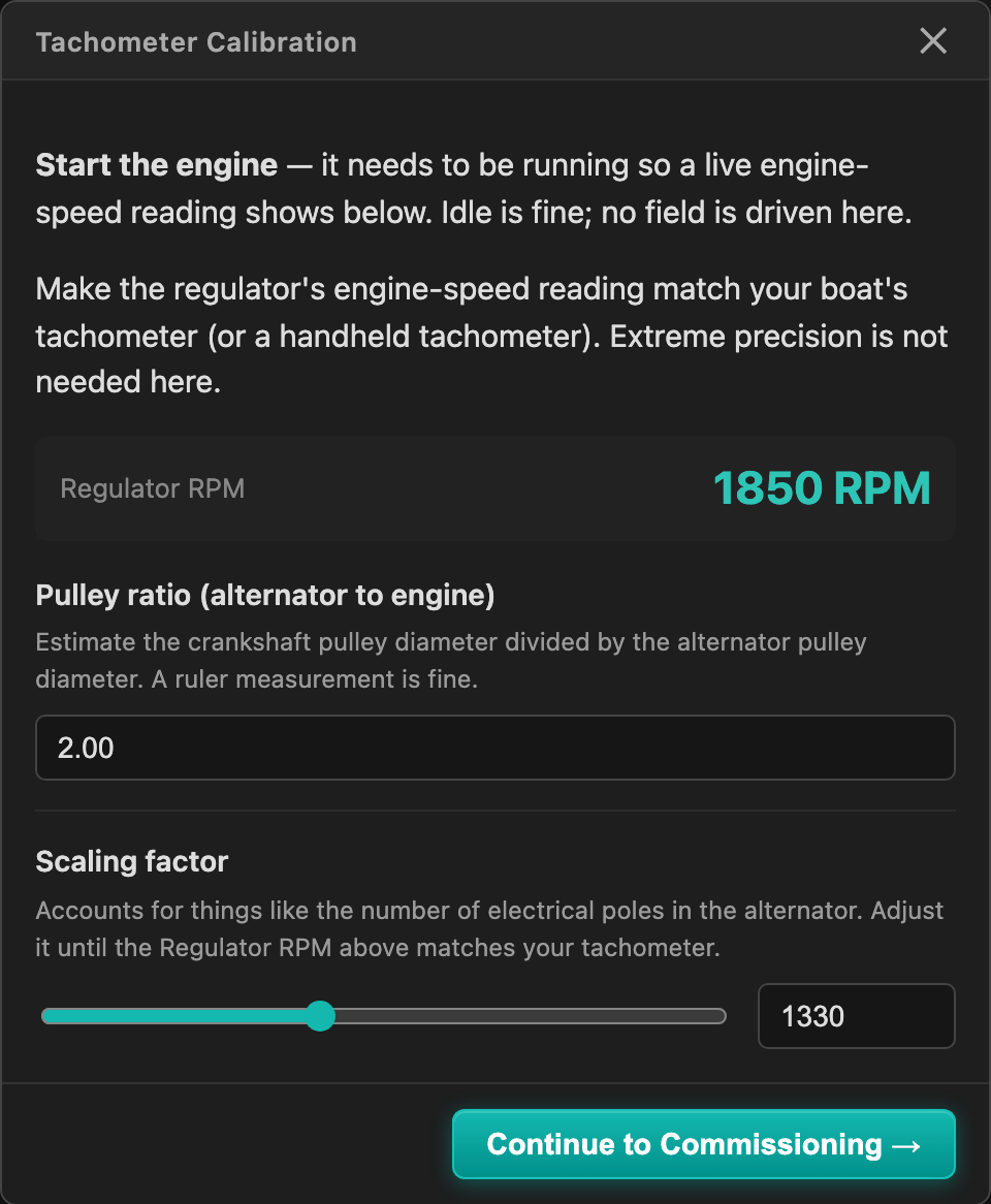
Both values remain editable later under Setup → Engine → Engine & Alternator Parameters.
4g. Automatic System Characterization
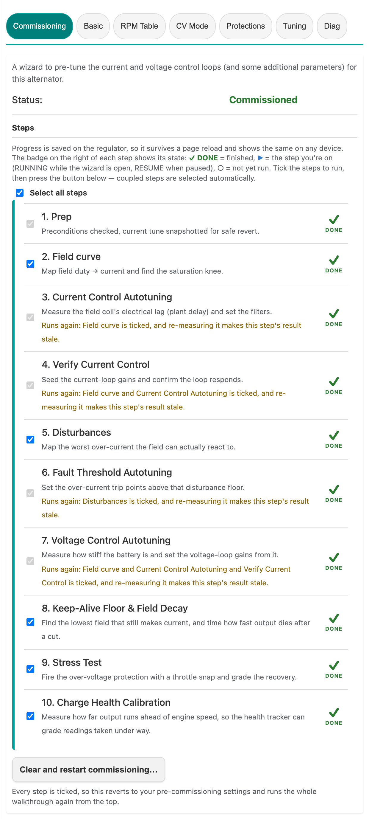
The chain ends by opening the characterization wizard, which measures your alternator and battery and sets the control-loop gains, filters, and protection thresholds from those measurements, which is why manual tuning is not part of this page. See Automatic System Characterization for the full walkthrough of its ten steps.
If you skipped it, start it any time from Setup → Alternator → Commissioning, the first tab in the Alternator row. When it has finished, that tab reads Commissioned with every step marked DONE:
5. The rest of Setup, tab by tab
Characterization sets the measured things. What follows is what it deliberately leaves to you, tab by tab through Setup. One tab is skipped here, Integrations, because its features (NMEA 2000 transmit, charge-limit follow) ship switched off and mostly matter on a networked boat; they are covered in External Interfaces. None of it blocks charging; treat it as a first-day pass you can refine later.
Setup → Temperature
The Temperature sub-tab holds the probes themselves: Temperature Sensors (which 1-Wire probe plays which role) and Extra Temperature (the Extra-role probe's live reading). What a probe feeds sits with its subject instead: the alternator thermal limits under Setup → Alternator → Basic → Temperature Settings, and the battery temperature with its charge lockouts under Setup → Battery → Charge Settings → Battery Temperature. All three places are covered here.
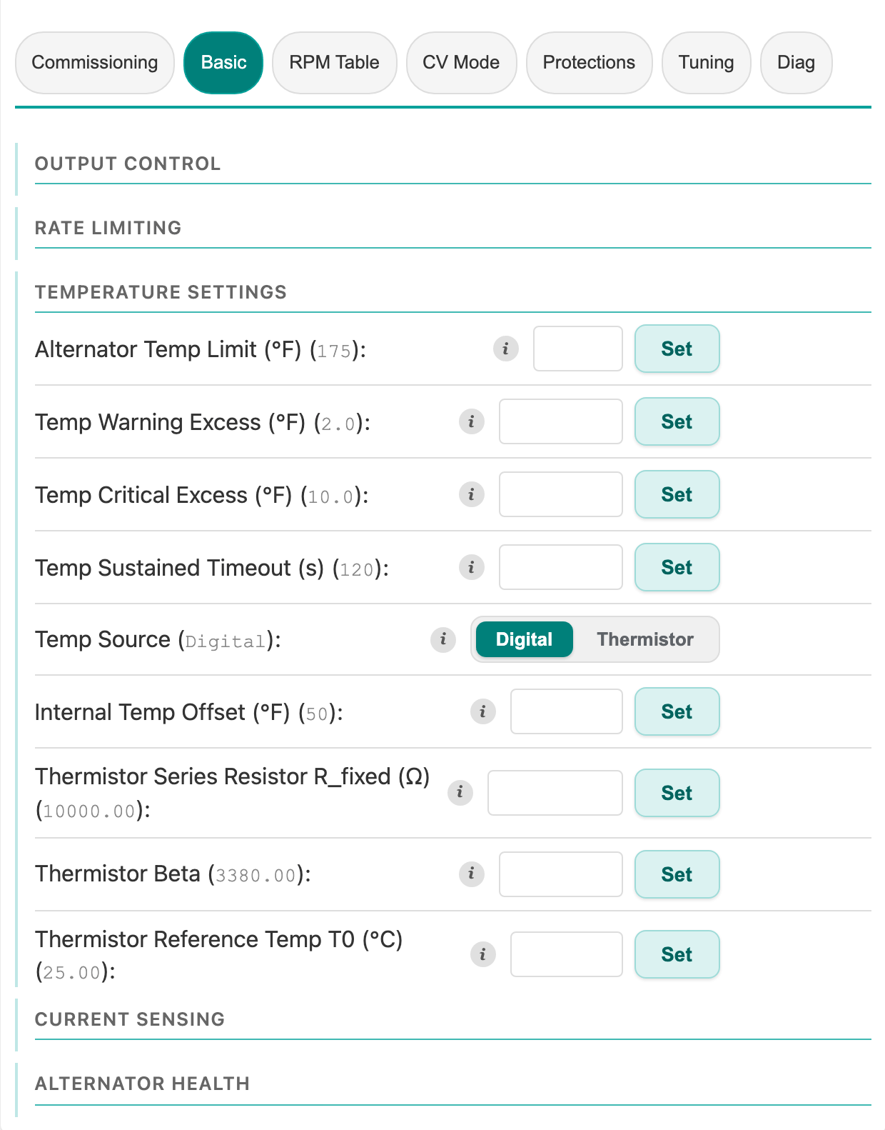
Alternator Temp Limit, under Setup → Alternator → Basic → Temperature Settings, is the ceiling the thermal loop derates against. Set it as a case temperature, not a winding temperature: the probe mounts to the alternator case, which runs roughly 40–50 °F cooler than the windings inside. A 220 °F continuous winding rating, typical for marine alternators, corresponds to something near 170–180 °F at the case, which is where the shipped default comes from. Entering the winding number directly would run the machine far hotter than its rating. Too low and you never reach rated output; too high and you cook the alternator.
Cold-Charge Lockout, in the Battery Temperature group under Setup → Battery → Charge Settings, blocks charging when the battery temperature falls below the Min Charge Temp threshold. It ships on, for lithium: charging LiFePO4 below freezing plates the cells permanently. Battery Temperature Source decides where that temperature comes from, and every option is a measurement taken at the bank. Assign one of the remaining probes to the Battery role in the Temperature Sensors group under Setup → Temperature, and switch on the Battery temperature probe toggle beneath that table (the Commissioning Prerequisites screen does both in one step). A battery temperature published on NMEA 2000, VE.Direct, or RV-C serves just as well. With no measured source the lockout never fires. Lead-acid banks charge cold just fine. The caveats, and the matching opt-in Hot-Charge Lockout, are on Safeties and Protections.
Setup → Alternator: RPM Table
The tables you seeded in the Charge Rate Limits screen live here, with more detail per row.
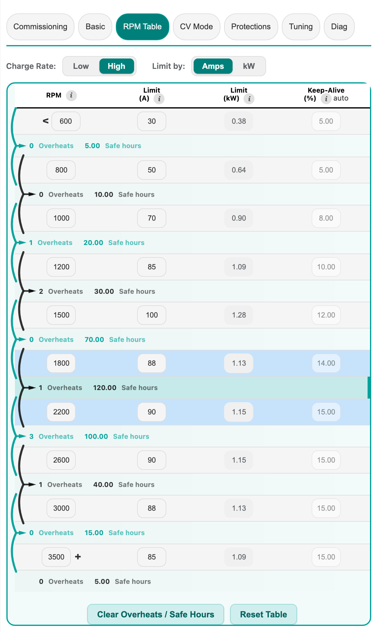
The Charge Rate: Low / High toggle both selects which table you are editing and switches the one the regulator runs against, so flip it here whenever you want the relaxed or the aggressive schedule. Limit by: Amps / kW is not a display choice: it selects which ceiling the regulator enforces. In Amps mode the numbers you type are a fixed current ceiling; in kW mode they are a power ceiling, and a separate kW table is divided by the live battery voltage on every control tick to derive the amp ceiling, so belt and shaft load stay constant as the bus sags or rises. The Keep-Alive (%) column is the per-speed tachometer keep-alive floor, learned automatically during characterization and afterwards; leave it on auto. Between the rows, the regulator accumulates per-speed overheat counts and safe hours: the evidence to look at before raising a limit.
Setup → Battery: charge phases
The Charge Settings panel's Phase Definitions accordion holds the per-phase voltages and criteria the recommendations just filled in.
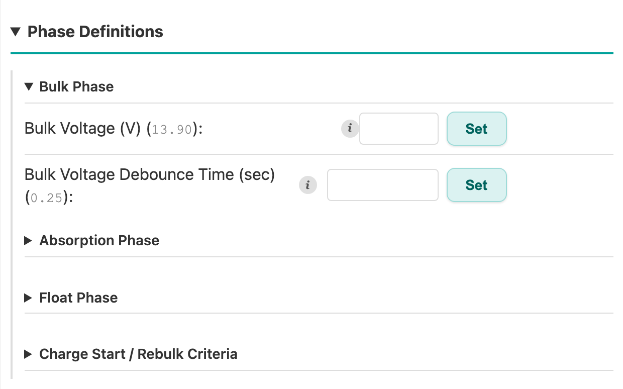
If you applied the recommendations, there is normally nothing to do here, but this is where bulk / absorption / float voltages and the rebulk criteria live when you want to check them against your battery's datasheet. The neighboring accordions (Safety, SoC Integration, Measurement Sources) hold the battery-side protection thresholds and the shunt configuration; the How It Works accordion at the bottom explains the whole charge cycle in prose. For the deeper story see Charging Control.
Setup → Battery: Battery Monitor
Switch the inner panel from Charge Settings to Battery Monitor. Two things matter on day one.
Full Charge Detection holds battery capacity and the full-charge criteria:
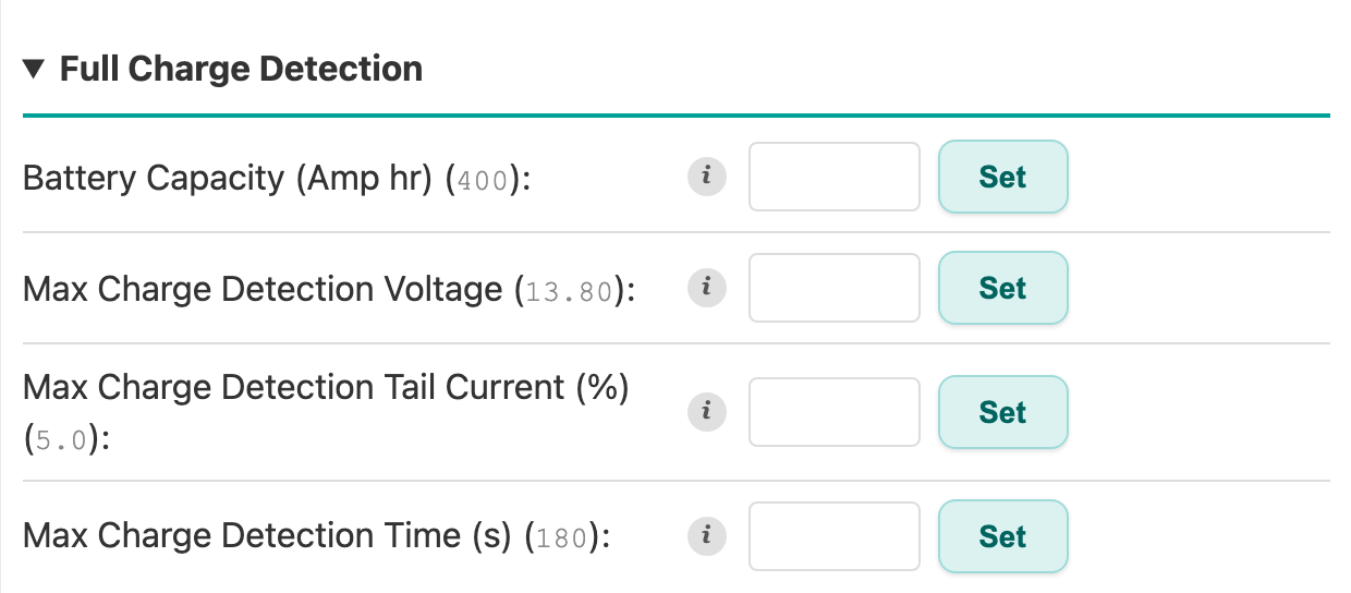
Battery Capacity (Amp hr) drives the charge counter (coulomb counter). Get it wrong and the state-of-charge display drifts. Match the bank's rated 20-hour capacity. Max Charge Detection Voltage must sit slightly below your bulk voltage so the bank reaches it during absorption. With the recommended values it already does (13.8 V against a 13.9 V bulk in the example). When voltage is above it and tail current below the threshold for the configured time, the counter re-anchors to 100 %.
Other Settings holds the manual override:
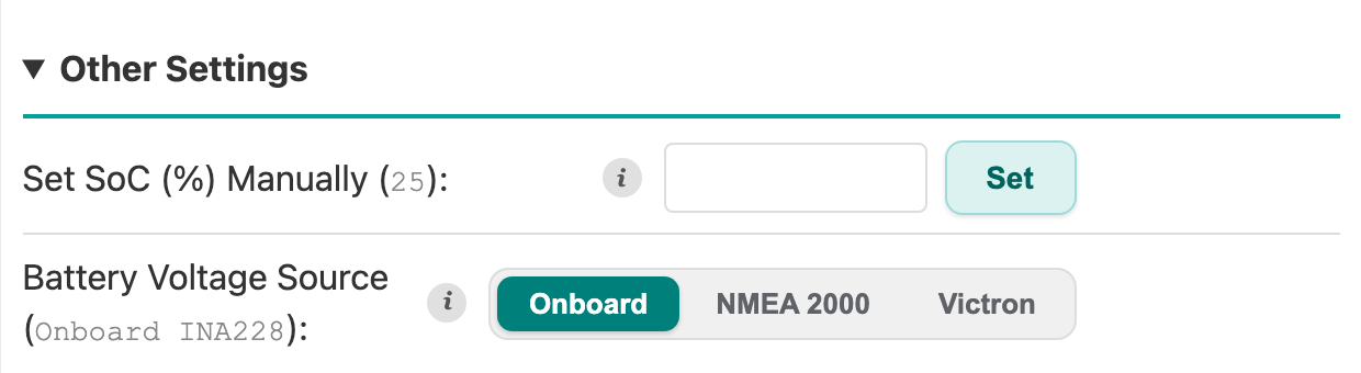
Same control as the popup in step 4c, available any time. The remaining accordions (Efficiency Parameters, SOC Correction) were set chemistry-appropriate by the recommendations: the Peukert exponent is 1.05 for lithium, 1.10 for AGM, and 1.25 for flooded.
Setup → Solar
If the boat has solar, the regulator can look up the solar forecast for your position (GPS, or home port as fallback) and skip alternator charging when the sun will do the job. A two-of-three forecast-day vote against your harvest threshold decides when it takes over (see Defer to Solar). While it holds the alternator off, the dashboard says resting — solar forecast is strong, so a quiet alternator on a sunny day is never a mystery.
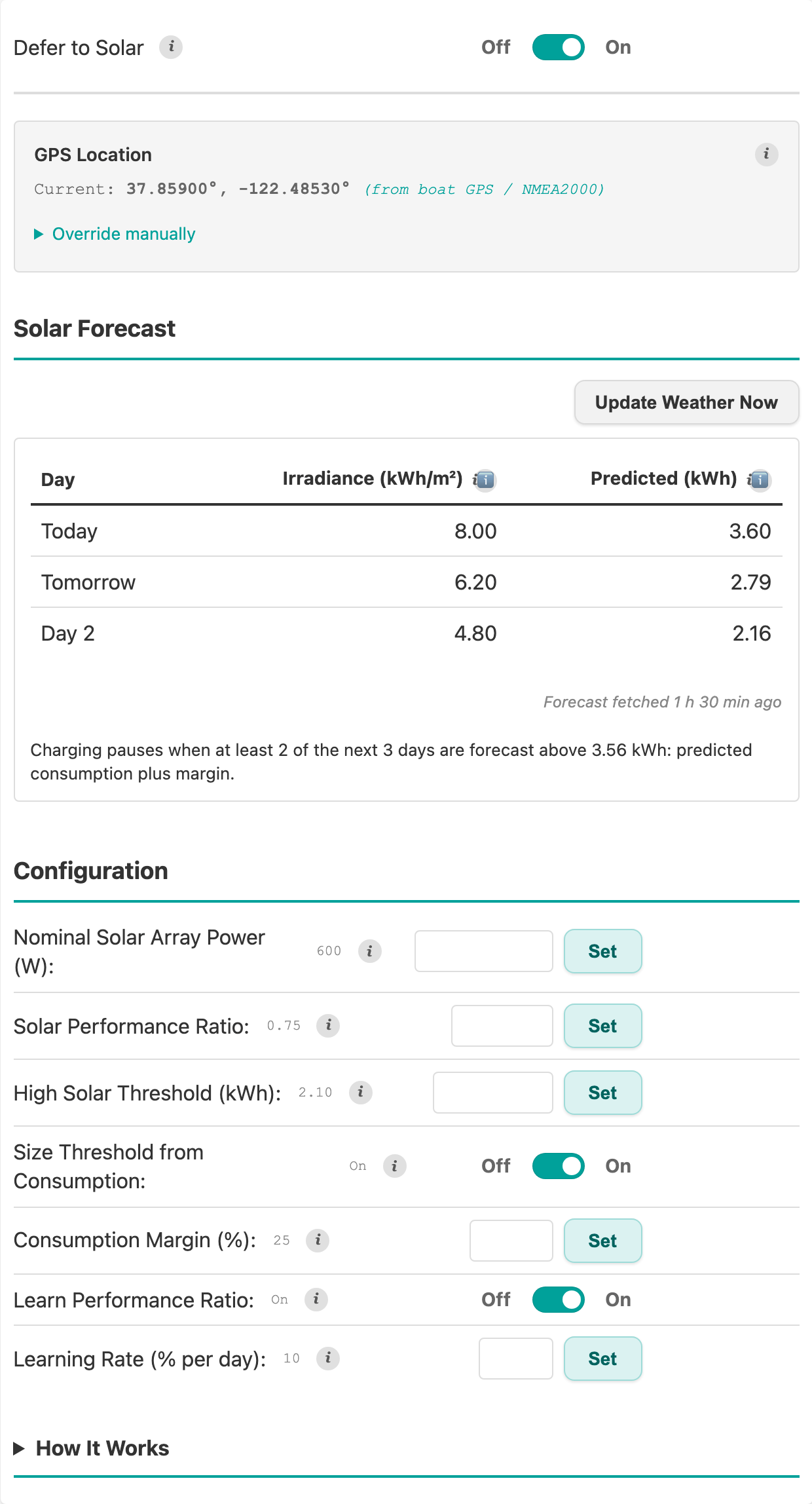
Defer to Solar ships disabled, so with no solar there is nothing to do here. If you have solar, turn it on; the default thresholds err on the side of charging whenever conditions are at all uncertain.
Two things worth knowing before you switch it on. The forecast comes straight from Open-Meteo, a public weather service, and that request carries your latitude and longitude. It does not travel through our servers, so the Cloud Features switch does not govern it. And the forecast block grays out, under an offline note, when the regulator is running its own hotspot (Access Point mode), because there is no internet behind it to fetch a forecast with. The position and array settings on the tab still save. A pause left over from the last fetch releases itself once the forecast goes stale, so charging always comes back on its own.
Two more switches on this tab ask nothing of you. Learn Performance Ratio lets the regulator correct the array's performance ratio from what the panels deliver each day, so the forecast fits your boat rather than a typical one. Size Threshold from Consumption swaps the fixed harvest threshold for what the boat has really been using, plus a margin, once a few days of history exist; until then the threshold you set stands in. The day-by-day record of what was predicted and what happened is on Live Data → Integrations, under Solar Energy Ledger. Seeing the harvest needs a Victron charger on VE.Direct; seeing consumption also needs the battery shunt.
Setup → Alarms
Personal-preference territory: every row here only decides when the buzzer sounds, never how the regulator charges. Walk through each threshold once and match it to your tolerance.
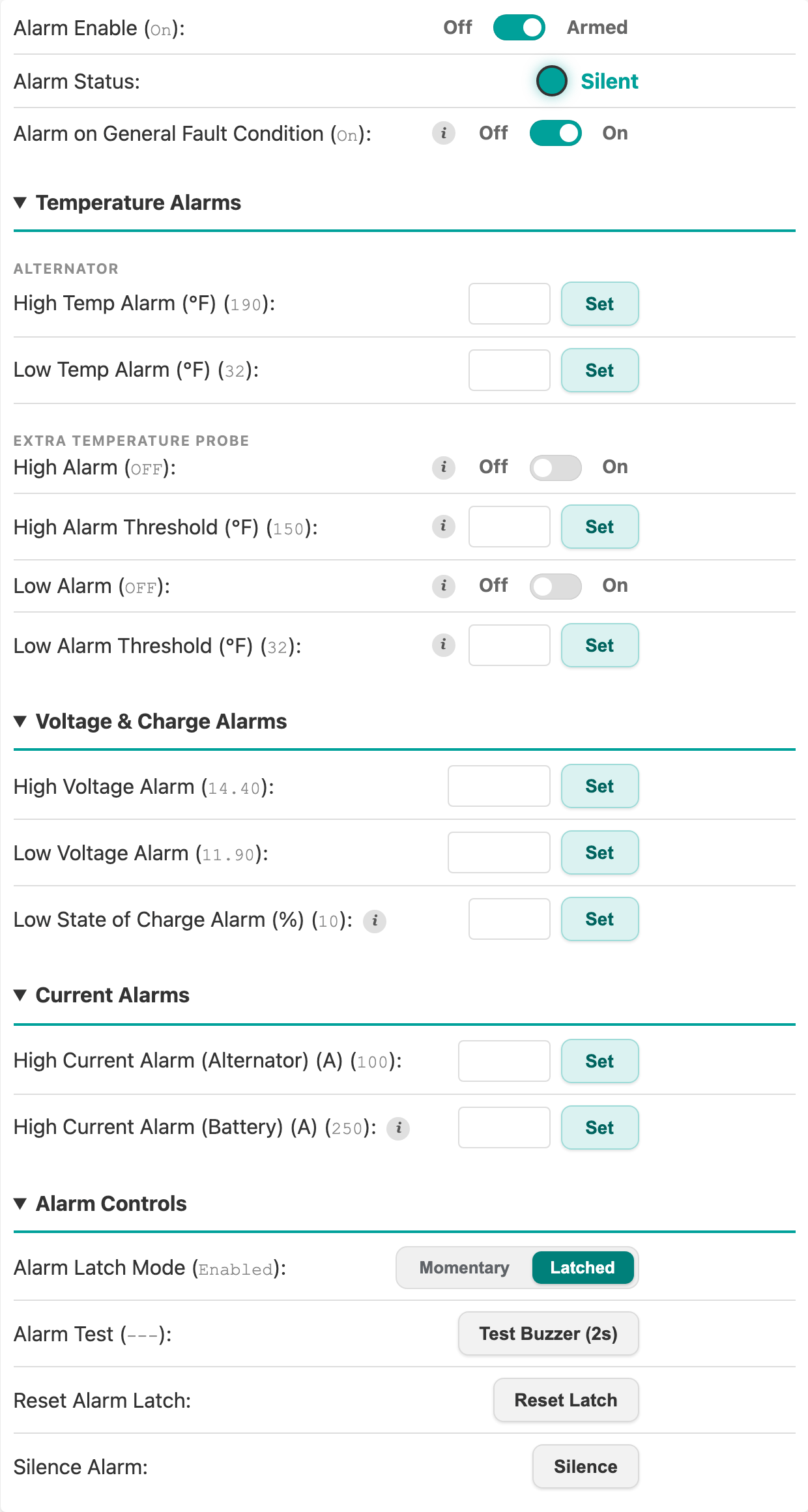
Alarm Enable is the master arm. Alarm Latch Mode decides whether an alarm keeps sounding after the condition clears (until Reset Latch); Test Buzzer proves the hardware. The cold and hot charge lockouts sound the same buzzer without a threshold row here. Faults with no threshold of their own (a sensor that stops reading, a lost measurement chip, the hardware over-voltage latch) sound while Alarm on General Fault Condition is on, as shipped. The alternator current pulse-pattern fault has its own Sound Alarm on Fault toggle under Setup → Alternator → Diag, shipped off.
Setup → Engine: Fuel Consumption
Fuel burn at each RPM breakpoint, for your engine. This drives the fuel-burn estimate and the per-charge fuel totals in Cloud Features. The column is in US gallons per hour or liters per hour, following the Fuel Volume Units preference under Setup → System → Display Preferences (US gallons as shipped); the figures below are gallons.
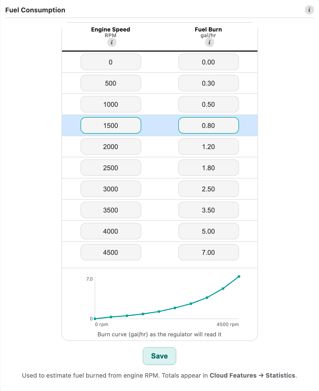
Sources, best to worst:
- Manufacturer's propeller curve: read GPH at each RPM off the datasheet.
- Your own data: a fuel-flow sensor or hand-calculated burn from past trips beats the datasheet because it reflects your actual loaded prop.
- Crude estimate: a naturally-aspirated diesel burns roughly 0.05 GPH per rated horsepower at cruise; a loaded 50 HP engine is about 2.5 GPH. A placeholder until real data exists.
On the Boat tab, the Performance Learning section drives the sailing/motoring speed learner; leave its Tuning accordion at defaults on day one.
Setup → Boat: Motion Events
How violent a roll, pitch, or impact has to be before the inertial sensor (IMU) logs it as an event.
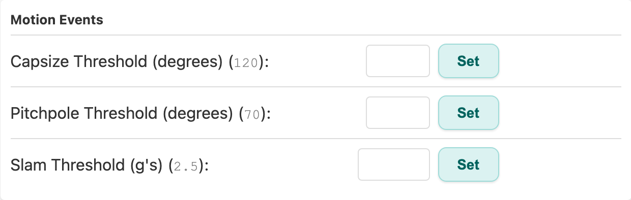
Defaults are reasonable. Revisit them after some real sea time, and only if events log too readily or not at all.
Setup → Engine, and Setup → System: relocking
The Engine sub-tab's Engine & Alternator Parameters accordion holds the two values from the Tachometer Calibration screen, editable by hand:
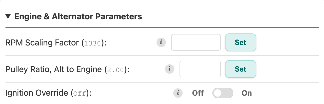
To touch up the scaling factor manually: run the engine at a known steady speed, compare the dashboard's reading to the tachometer, and multiply the current factor by (tach ÷ dashboard). Two iterations usually nail it; within 50 RPM is fine. The pulley ratio only feeds the alternator-lifetime physics model; the control loop uses measured engine speed directly.
Ignition Override sits in the same accordion. Off, the regulator counts the ignition as on only while the key is on, and charges only then. On, it counts the ignition as on all the time, so charging no longer waits for the key; the alternator switch turns it on and off. Turn it on when no ignition wire is connected to the regulator. With it on, the regulator stays fully awake while the engine is off and draws more power at rest (see How much power it uses).
When you are done making changes, Security & Maintenance under Setup → System has the button that ends the settings window. The window never closes on a timer, so it stays open until you press this or the regulator reboots.
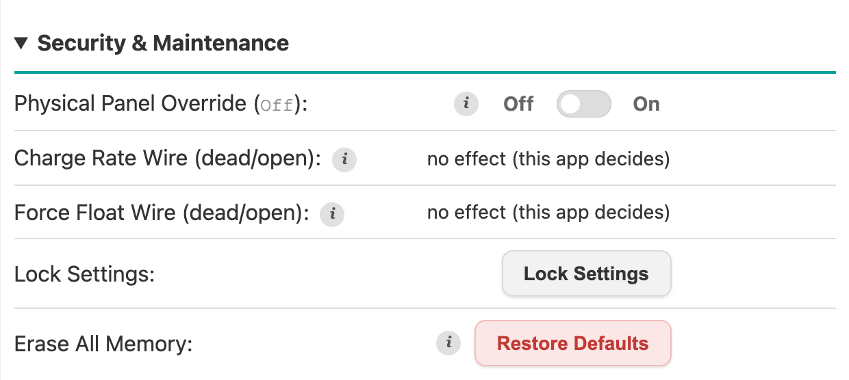
The other System accordions can wait; none of them needs attention on day one.
6. Check normal charging
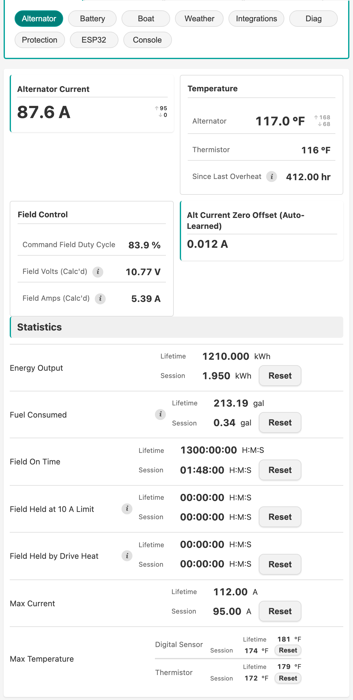
With settings done and characterization finished, run the engine and open Live Data → Alternator: current flowing, field duty tracking, temperature climbing gently, voltage rising toward bulk. The header strip shows the same numbers from anywhere on the boat.
Two more things worth doing while you are aboard:
- Register for Cloud Features in the Cloud Features tab: history upload, firmware updates (OTA), and leaderboards.
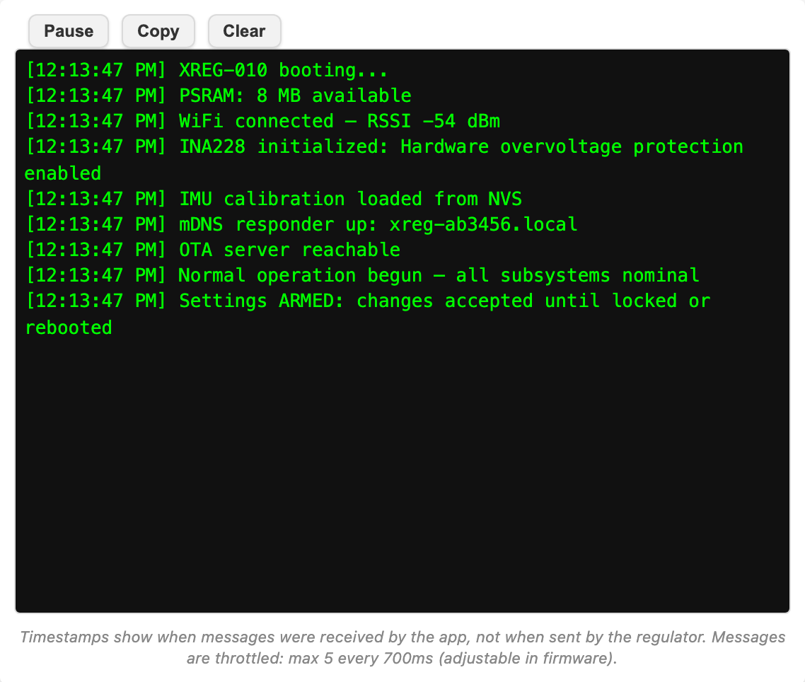
- If anything misbehaves, Live Data → Console streams the firmware's own status messages live, usually the fastest way to see what it is unhappy about. See Troubleshooting for the common failure modes.
Common Settings gotchas
Dashboard refuses to leave Setup. All tabs outside Setup are blocked until Vessel Info is complete. Fill in all required fields and click Save.
Lost WiFi password. Ground the GPIO45 recovery wire at boot to re-enter configuration mode with default credentials. See Connecting to the Regulator → Override wires. The same recovery clears the optional settings password, if one is set.
SoC drifts noticeably after a day. The most common cause is wrong Battery Capacity (Amp hr) in Setup → Battery → Battery Monitor. Second most common is full-charge detection never firing. Verify Max Charge Detection Voltage sits slightly below your bulk voltage so the bank reaches it during absorption.
A high-voltage alternator with a 12 V field winding. Manufacturers commonly reuse one 12 V field winding across their 24 V and 48 V models, so a 48 V machine can hold a part that is still rated for 12 V. Max Field Volts in Setup → Alternator → Basic caps the field in the units the alternator datasheet uses. The regulator ships assuming a 12 V winding, so on a 24 V or 48 V bank it is the setting that limits field drive until you enter a higher rating from the datasheet. Above that, the board's own 10 A field-current ceiling or its drive-heat ceiling can be what holds the field, and the header says which (10 A FIELD or DRIVE HEAT beside the duty). What each ceiling protects against, and what it does not, is on Charging Control → The field ceiling.
DRIVE HEAT on a hot day. The regulator is holding the field down to keep its own field drive inside its temperature rating, and output returns as it cools. A cooler mounting location raises the limit. Check that Field Wiring is set: while it is not set, both the P-type and the N-type checks run and the lower one wins. Check too that Field Resistance came from the field resistance test and not from an ohmmeter, since both board ceilings are calculated from it.
Skipped part of the guided chain and want it back. Everything the chain sets lives under Setup (this page says where, screen by screen), and the characterization wizard re-runs any time from Setup → Alternator → Commissioning, its prerequisites screen included.
Cross-references
- Connecting to the Regulator: previous step in the installation flow.
- Automatic System Characterization: the guided measurement run this page hands off to.
- Alternator Type and Power/GND/Field wiring: which type you have, then P-type or N-type for hardware wiring and fusing.
- Charging Control: what the charge phases and maintenance behaviors do.
- Troubleshooting: common failure modes.