Unboxing
The kit omits items that are boat-specific (such as Ethernet cables — different lengths being necessary), generic items most customers already have (battery shunt), and accessories (connectors, fuses, switches). However, recommendations for these extras are provided below for convenience.
What's in the box
| Item | Qty | Photo | Notes |
|---|---|---|---|
| Regulator | 1 | 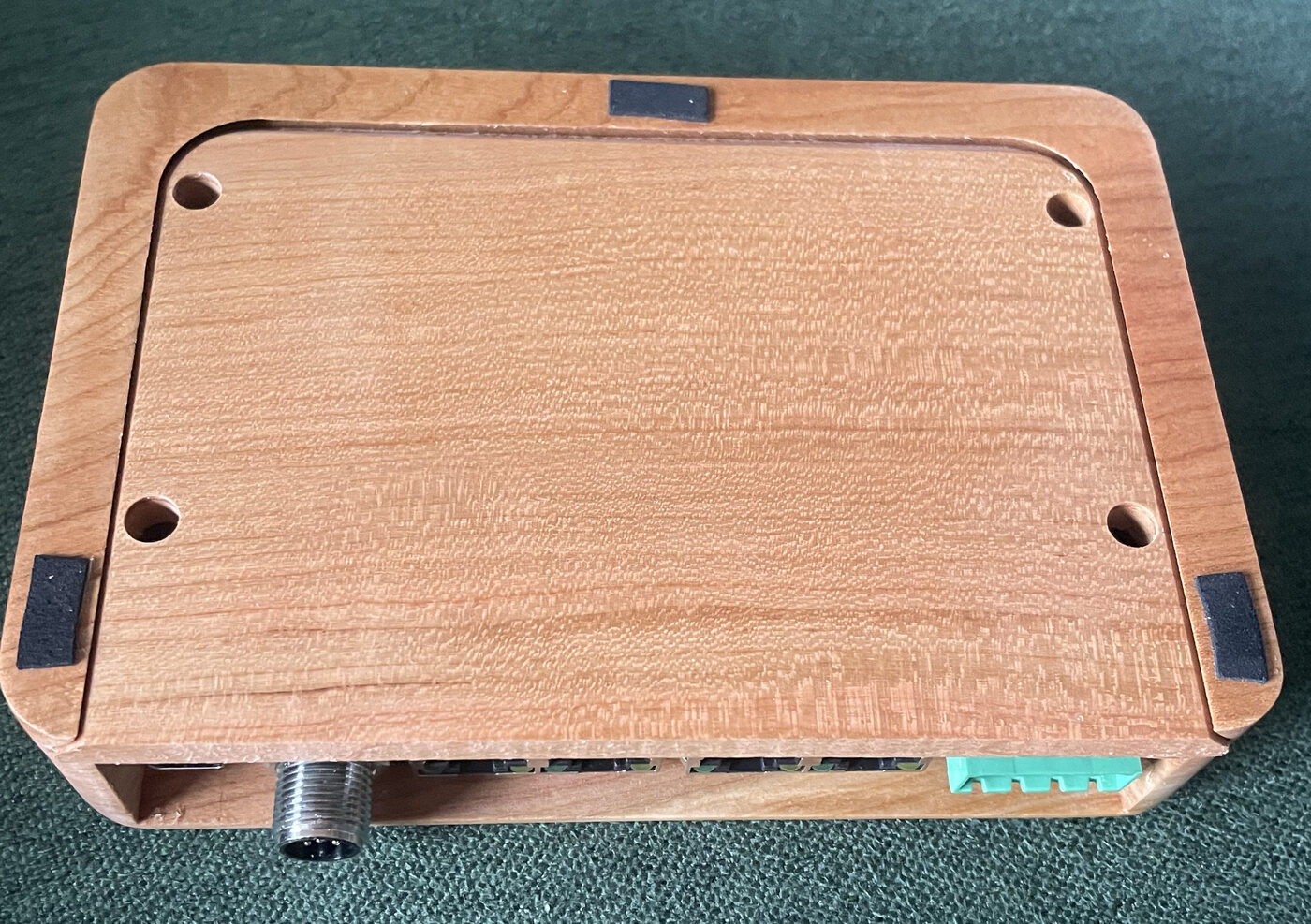 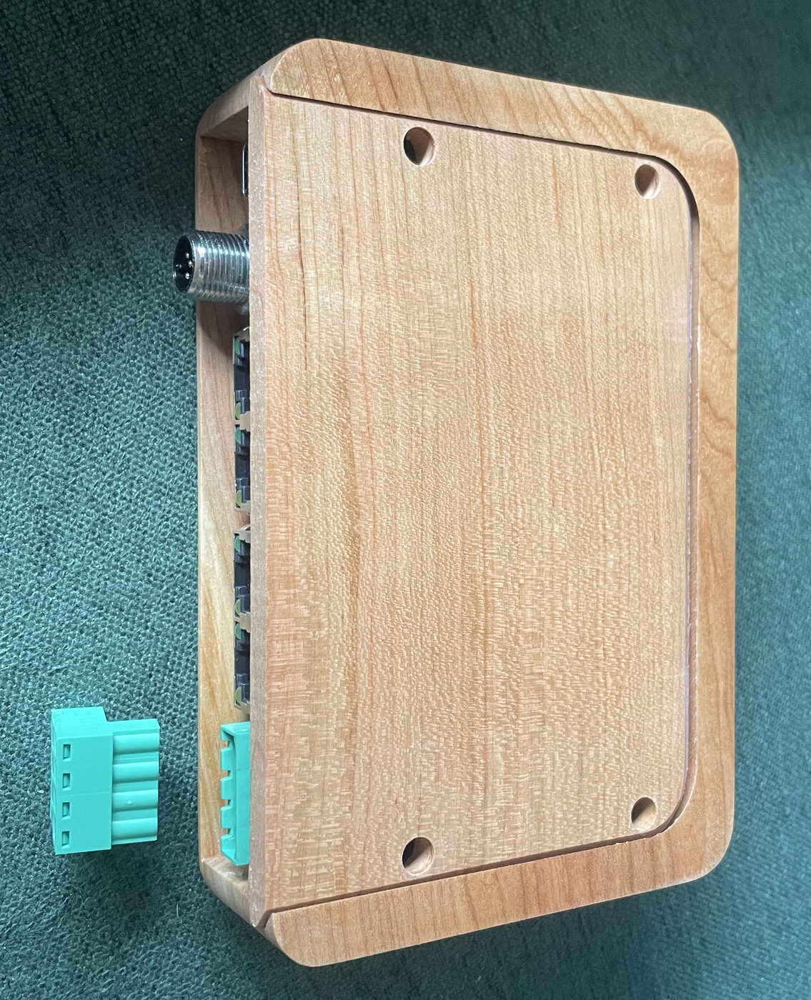 |
PCB in its wood enclosure, mounted to the Base, with harness plug. Felt tape wall bumpers are already installed on the Base |
| 316 stainless screws | 9 | 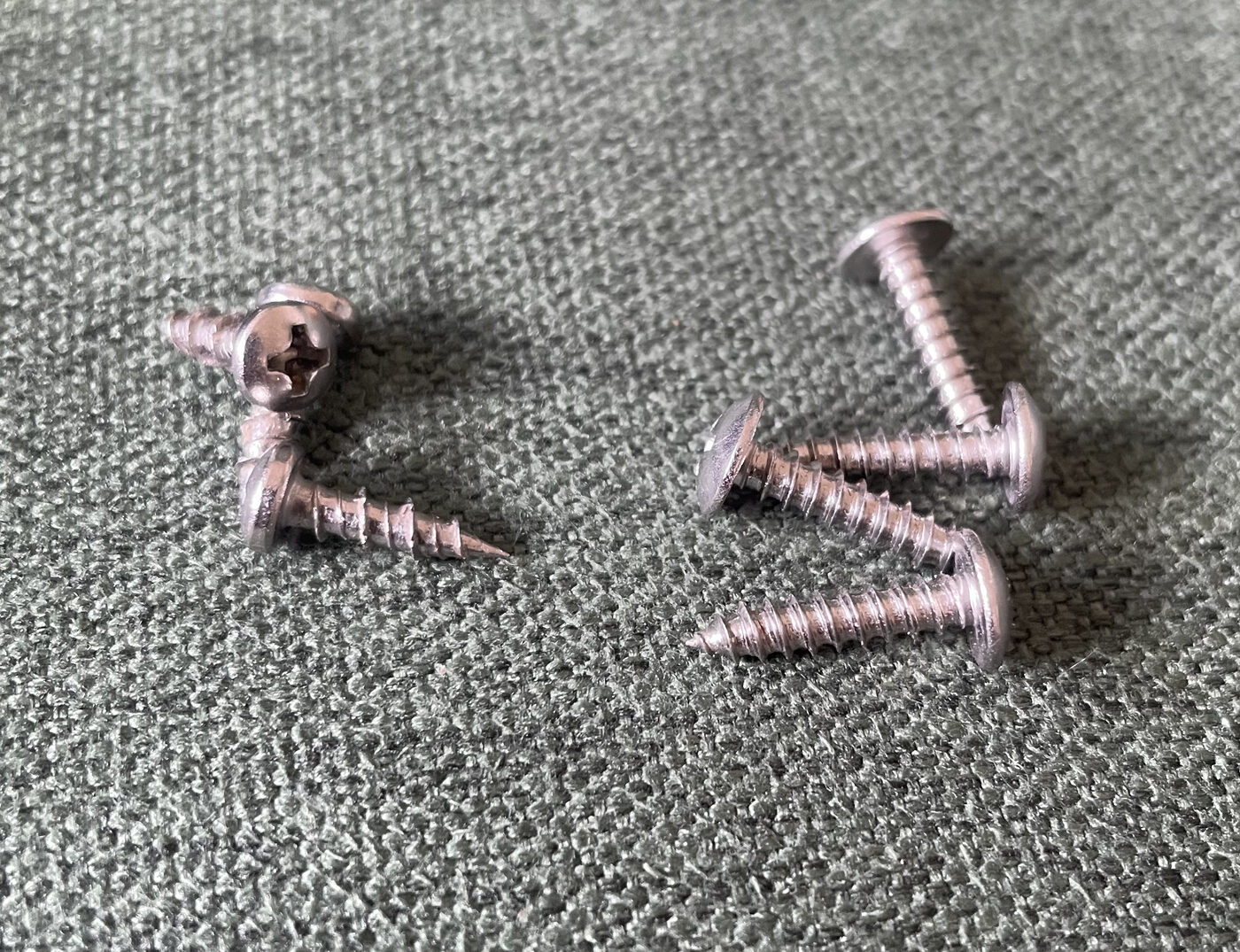 |
3 for mounting the PCB to the Base (already done), 4 for mounting the Wall Dock to the bulkhead, and 2 for the alternator current sensor |
| Plastic washers | 3 | 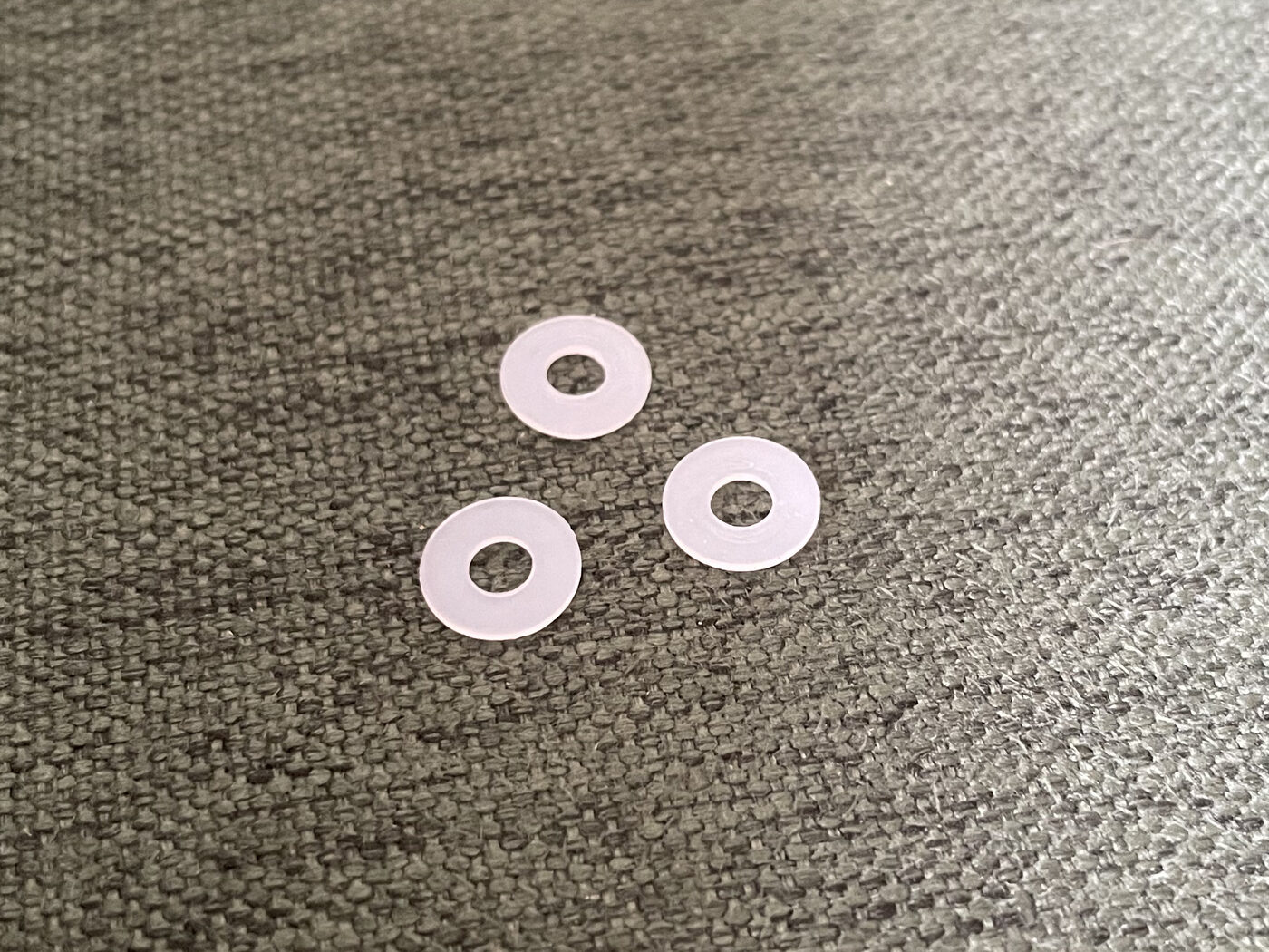 |
For the PCB mounting screws, already installed |
| Heat-shrink labels | 4 | 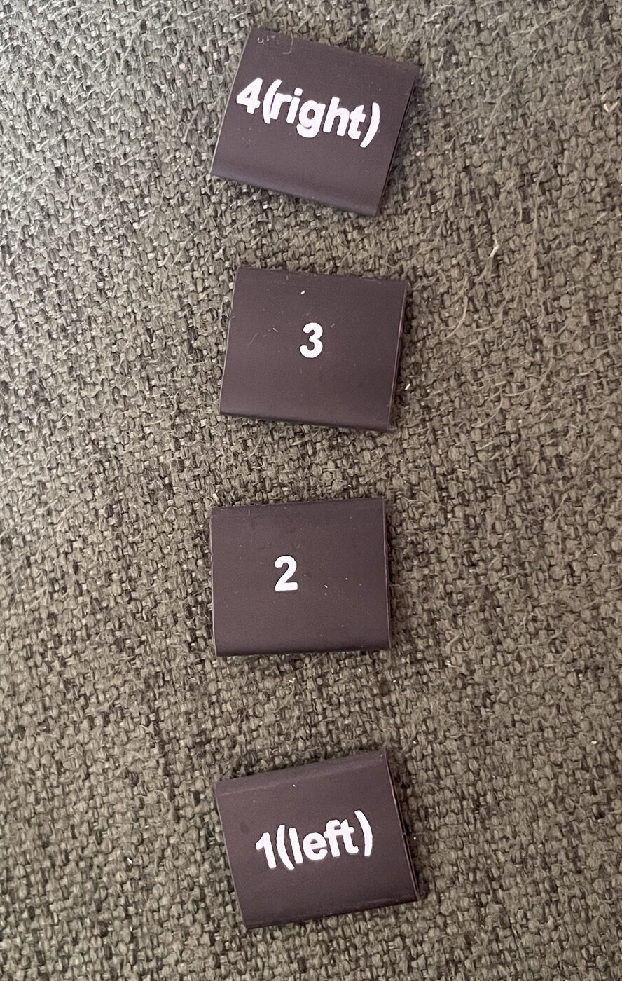 |
For labeling the four Ethernet cables (1left, 2, 3, 4right), helps your future self prevent mixing |
| Bulkhead drilling template | 1 | 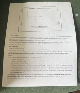 |
Paper template for the mounting holes |
| Digital temperature sensors | 3 | 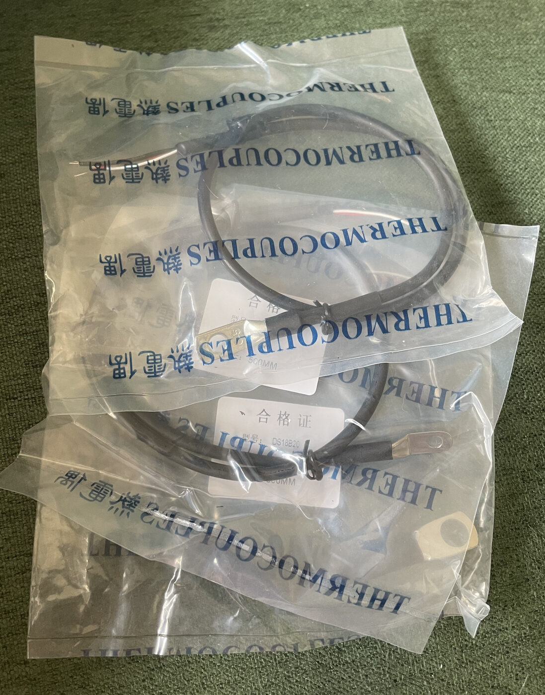 |
One each in M4, M5, and M8 lug sizes — pick the ones that fit your installation best, and contact X Engineering if other sizes are required |
| Alternator current sensor | 1 | 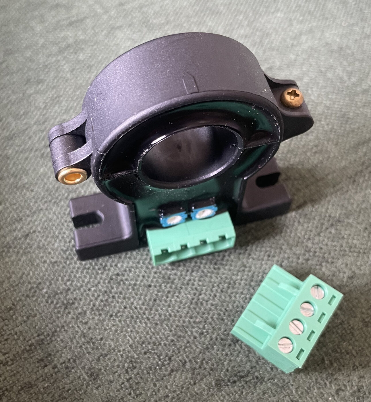 |
300 A range, with harness plug |
| P/N alternator configuration jumper | 1 | 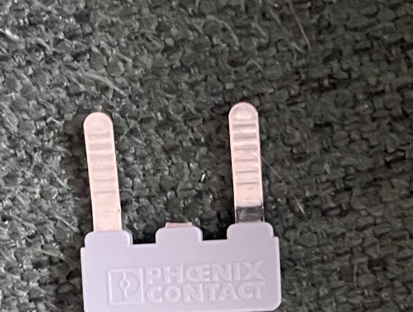 |
Sets the board for a P-type or N-type alternator — see Alternator Type and Power/GND/Field wiring |
| Packing List and Quick Start | 1 | 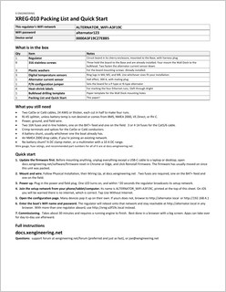 |
Printed page with WiFi info specific to each regulator |
What else you'll need
| Item | Qty | Photo | Notes |
|---|---|---|---|
| Power, ground, and field wire | 3 runs | 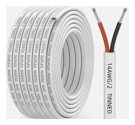 |
Most retrofits can reuse the wiring already on the boat for the power and field runs, including 14 or 16 AWG. The ground run is the exception: it must be 12 AWG, and as short as the layout allows, because its gauge and length shift the battery voltage reading. For any run you are replacing, use 12 AWG marine-grade stranded tinned copper. |
| Inline fuses | 5, or 6 with a BMS | 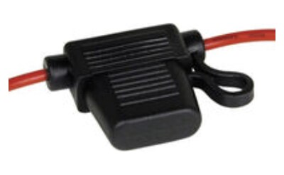 |
Two 10 A on 12 AWG holders, one on the input power and one on the field. Then 1 A on an 18 AWG holder for each Cat6 conductor that taps boat power: Cable 2 pin 11 at the battery, Cable 1 pin 4 at the stator, Cable 3 pin 6 at the ignition, and Cable 2 pin 16 at the BMS output where one is fitted. On 12 and 24 V, Sherco USATC10 and ATO1A fuses, 32 V DC, in Sherco IHWOM12HD and IHWO18 waterproof in-line holders. On 36 and 48 V, OptiFuse ANR80-UL-10A and ANR80-UL-1A fuses, 80 V DC, in OptiFuse LPR-02B-12R and LPR-02B-18R in-line holders, which their maker rates 125 V DC and IP67. Choosing the fuses |
| Ethernet cable, Cat5e or Cat6 | 2 |  |
Stranded, 24 AWG or thicker. Cut each of the cables in half to make 4 total runs. Recommended: CableWholesale Cat5e shielded (STP), 24 AWG. Which lengths to buy · 22 AWG marine-duty upgrade |
| Crimp terminals and splices | as needed | 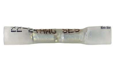 |
Butt splices, step-ups and ring terminals for the Cat6 conductors. Every part number, per pin: Data Cables & Pinout |
| Battery shunt | 1 | 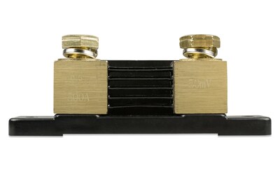 |
Whatever your boat has is probably fine — the shunt is software configurable in Setup. Recommended: Victron SHU500050100, 500 A / 50 mV |
| NMEA 2000 drop cable | 1, optional | 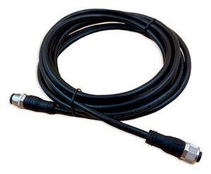 |
Any generic drop cable. Buy whatever length reaches your backbone. Recommended: Digital Yacht NMEA 2000 drop cable |
| Control switches | optional | 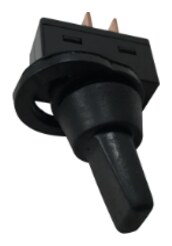 |
None are required, but they are convenient for controlling WiFi modes, resets, Hi/Low mode and so on. Which switch to buy and how to wire each one: Control Switches |
| Alarm buzzer | 1, optional |  |
Must draw <250 mA on a 5 V supply, and be self-driving (AC excitation not required) — the regulator drives it directly with DC. Recommended: Raltron RBE-4.000-3215-NS1, 10 mA, 95 dB |
| RJ45 splitter | 1 | 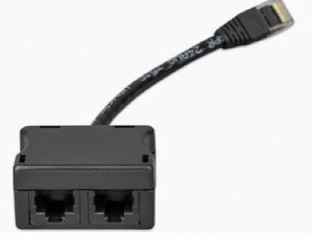 |
Carries the Battery Temperature Sensor in parallel with Cable 1. Battery temperature has to be measured at the bank, so you need the splitter unless a BMS, NMEA 2000, VE.Direct, or RV-C source publishes it. Must be straight-through (all 8 pins to both jacks), not a pair-splitting type. Recommended: Victron Energy RJ45 Splitter, 1 Male to 2 Female, ASS030065510, $19 |
| DC clamp meter or multimeter | 1 | 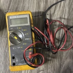 |
Only needed on a 24 V and up system with no battery shunt wired to the regulator, or if the field resistance test reports that the shunt is not seeing the field current. The regulator needs to know the field's resistance, and this is measured automatically when a battery shunt is present. Without a shunt, field current during the field resistance test must be measured manually with a DC clamp meter (a Hall-effect type; an AC-only clamp reads nothing on DC) or a multimeter with a 10 A DC range. A 12 V system with no shunt can skip the test instead. The procedure is in Initial Settings. |
The four Ethernet runs go from the regulator to:
| # | Run |
|---|---|
| 1left | Alternator area |
| 2 | Battery bank area |
| 3 | Ignition switch / ECU area |
| 4right | Nav / Control / Networking area |
You supply your own fusing. Two at 10 A, one on the regulator's power feed and one on the field wire, matching the regulator's 10 A field output rating. Then 1 A on every Cat6 conductor that taps a source of power outside the regulator: Cable 2 pin 11 at the battery, Cable 1 pin 4 at the stator, Cable 3 pin 6 at the ignition, and Cable 2 pin 16 at the BMS output where one is fitted. All are ATO blade fuses, and which one you buy depends on the system voltage.
The 1 A fuses protect 24 AWG Cat6 rather than anything on the board. NEC Table 725.144 rates that conductor at 2.0 A in a single 4-pair cable and lower where cables share a bundle, and these wires carry milliamps, so the fuse sits well under the limit instead of at it. Every other conductor on the four cables is grounded, fed from the regulator's own current-limited rails, or lands on a device output with no source behind it, so none of those are fused.
| Circuit | 12 V and 24 V | 36 V and 48 V |
|---|---|---|
| Power | 10 A / 32 V — Sherco USATC10 | 10 A / 80 V — OptiFuse ANR80-UL-10A |
| Field | the same fuse, 10 A / 32 V | the same fuse, 10 A / 80 V |
| Cat6 taps | 1 A / 32 V — Sherco ATO1A | 1 A / 80 V — OptiFuse ANR80-UL-1A |
A standard blade fuse off an auto-parts rack is rated 32 V DC. Above its rating a fuse can hold an arc across the melted gap instead of clearing the fault, and a 48 V bank absorbs near 58 V, which is why 36 and 48 V take the 80 V part. Holders carry their own rating too, and most inline ones are marked 32 V DC whatever wire is on them; on 36 and 48 V the OptiFuse LPR-02B-12R is rated 125 V DC and IP67 by its maker, on 12 AWG leads. The Sherco IHWOM12HD, also on 12 AWG leads, is the waterproof 12 and 24 V counterpart.
The 1 A fuses go in 18 AWG holders instead, which is the finest lead these are made on and splices to a 24 AWG Cat6 conductor in a single step-down crimp: Sherco IHWO18 on 12 and 24 V, OptiFuse LPR-02B-18R on 36 and 48 V.
Both holders and the fuse part numbers by system voltage: Fusing on the P-type or N-type wiring page.
You'll cut two cables in half to make four runs. A cable can be cut at any point — it does not have to be the middle. So a single 10 ft cable can become a 7 ft run (say, to a battery) and a 3 ft run (say, to a control switch). Add up the lengths your boat needs and buy cables that cut down into those lengths.
A pair that suits most boats: a 14 ft and a 25 ft (about $10.86 and $17.03 at the time of writing). Cut the 14 ft into a 4 ft and a 10 ft, and the 25 ft into a 5 ft and a 20 ft — four runs of very different lengths for well under $30. Measure your four routes first, then pick the two lengths that cut down to fit them.
The recommended CableWholesale cable is shielded and 24 AWG, sold in many lengths off the same page. Thicker conductors are mainly for ease of handling — these runs are not current-limited for anything the regulator does. Shielded (STP) is optional.
L-com TRD524HF-BLK is a factory-terminated 4-pair Cat5e assembly built on 22 AWG stranded conductors, with a TPE jacket rated −40 to +75 °C, resistant to oil, chemicals, UV and moisture, and rated for 10 million flex cycles. Stock lengths are 1, 5, 10, 15, 50, 100, 150 and 200 ft.
Three reasons to consider it. It is a much better cable for an engine room than a PVC patch cord. A bigger conductor is nicer to handle — easier to strip and easier to get into a crimp barrel. And 22 AWG drops straight into the common 22–18 AWG crimp terminals, so no conductor ever has to be folded back on itself to fill a barrel — see Data Cables & Pinout.
The cost difference is about $110 for a boat. Two 15 ft assemblies run roughly $138 against about $28 for the pair of patch cables above — call it five times the price for the same four runs. Their pricing is not linear across lengths, so check the current price for the length you need.
Cross-references
- Install Firmware First — put the current release on the unit over USB before it is mounted
- Alternator Type and Power/GND/Field wiring — which type you have, then P-type or N-type for wiring, fusing, and wire sizing
- Current Sensor — installing the 300 A clamp-on sensor
- Temperature Sensors — mounting the lug and wiring the leads
- Warning Buzzer — buzzer drive circuit details
- Data Cables & Pinout — connector pinouts
- Connecting to Regulator — power-up and WiFi