Alternator Type
Before wiring, determine whether your alternator is P-type (high drive) or N-type (low drive). This dictates which field terminal you connect to and which jumper you install on the board. This page also covers what the board's input protection tolerates, so you know what wiring mistakes it can and cannot forgive.
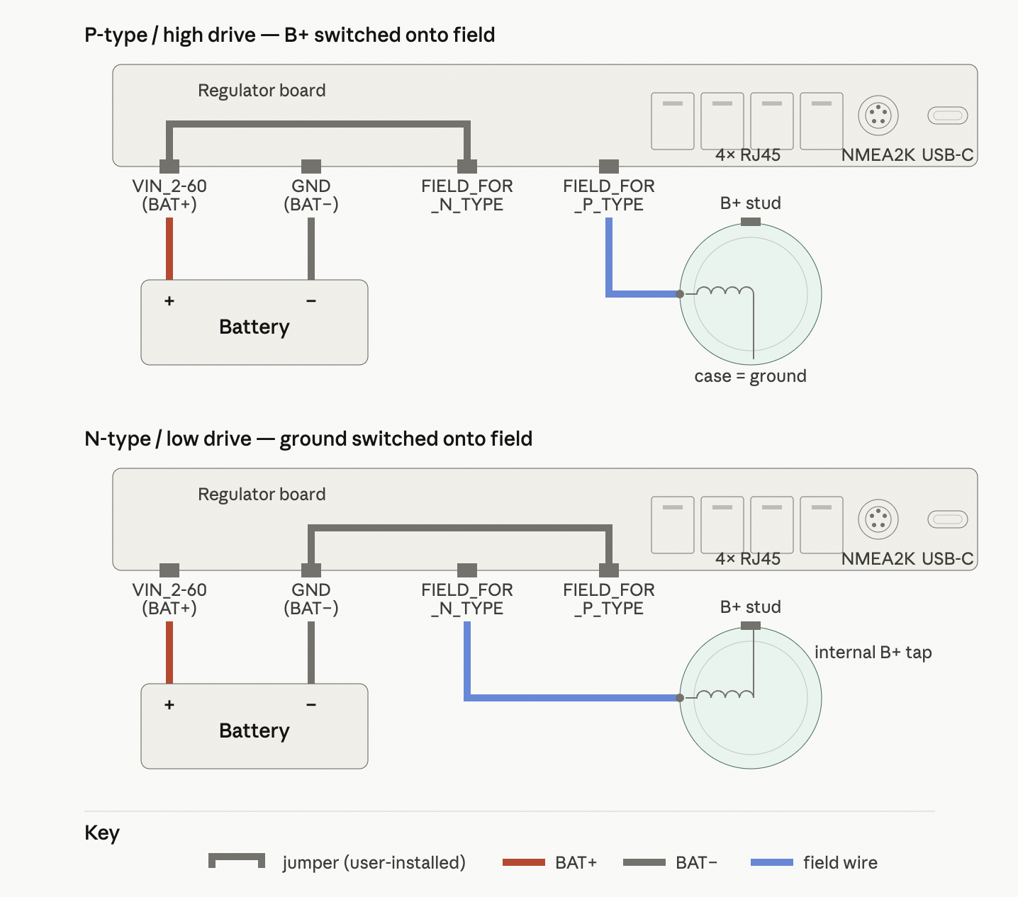
P-type alternator (high drive)
A P-type alternator has the field winding's far end internally bonded to the alternator case (chassis ground). The single field wire emerging from the regulator-side brush is switched to B+ by the regulator to excite the field.
- Field wire to: field-positive terminal (FIELD_FOR_P_TYPE)
- Jumper installed: BAT+ input to drain (VIN_2-60 ↔ FIELD_FOR_N_TYPE)
- External clamp module: not required
- External field fuse: not required — the board's input protection covers the field path
Field current path (output on):
battery (+) → board BAT+ input (VIN_2-60) → jumper → Q3 → field-positive terminal (FIELD_FOR_P_TYPE) → field wire → field winding → alternator case → engine ground → battery (−)
N-type alternator (low drive)
An N-type alternator has the field winding's far end internally tied to B+ (typically at the alternator's diode trio or an internal B+ tap on the rectifier). The single field wire emerging from the regulator-side brush is switched to ground by the regulator to excite the field.
- Field wire to: field-negative terminal (FIELD_FOR_N_TYPE)
- Jumper installed: source to ground (FIELD_FOR_P_TYPE ↔ GND)
- External clamp module: required — see Appendix A of the Alternator Field Drive doc
- External field fuse: required, sized to the alternator's rated field current
Field current path (output on):
battery (+) → alternator B+ stud → internal tap → field winding → field wire → field-negative terminal (FIELD_FOR_N_TYPE) → Q3 → jumper → board ground (GND) → battery (−)
Note
In N-type mode, field current does not pass through the regulator's BAT+ input (VIN_2-60). The board sees no field current on its protected supply rail.
Quick reference — alternator type
| P-type / high drive | N-type / low drive | |
|---|---|---|
| Field wire to | FIELD_FOR_P_TYPE | FIELD_FOR_N_TYPE |
| Jumper | VIN_2-60 ↔ FIELD_FOR_N_TYPE | FIELD_FOR_P_TYPE ↔ GND |
| Regulator switches | B+ onto field | Ground onto field |
| External clamp module | Not required | Required |
| External field fuse | Not required | Required |
Board Input Protection
The regulator's BAT+ input is protected by an automotive-grade high-side protection (eFuse) (TPS48000-Q1). Key protections relevant to installation:
- Reverse polarity: The board tolerates reverse battery connection to −65 V. It won't power up, but it won't be damaged by a briefly reversed connection.
- Overvoltage (OVP): Trips in the 60–65 V range and isolates the board in ~5 µs. Recovers automatically when voltage drops.
- Overcurrent (SCP): Trips at ~15 A sustained input current with a ~14 ms delay. This is a sustained-fault detector, not a cycle-by-cycle limiter — brief peaks during PWM switching do not trip it.
- Transient protection: A TVS diode across the input clamps fast spikes from load dumps, inductive transients, and lightning-coupled surges conducted through vessel wiring.
N-type installations
In N-type mode, field current bypasses the board's input protection entirely — see the fusing section on the Wiring page. The external field fuse is the only protection for the field circuit in that configuration.
For full technical detail on trip levels, timing, and circuit architecture see the Input Protection hardware doc.
Next step
Continue to Power & Field Wiring for wire sizing, termination, the jumper install procedure, and fusing.