QNHCK1-21 Hall Current Sensor
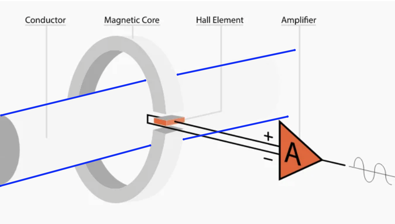
This is a split-core, open-loop Hall-effect current sensor. The high-current cable passes through the center opening and is electrically isolated from the sensor. Current in the cable creates a magnetic field. The magnetic core (split for installation convenience, but magnetically coupled) guides and concentrates that flux around the conductor and through the Hall sensing region. The Hall element converts magnetic flux density into an electrical signal, and the amplifier/calibration circuitry converts that into the analog output voltage.
For the ±300 A version included: 0 A ≈ 2.5 V, +300 A ≈ 4.5 V, and -300 A ≈ 0.5 V, giving roughly 6.7 mV/A. Current in the opposite direction drives the output to the opposite side of 2.5 V.
Teardown photographs (of a 200 amp model I chose to sacrifice)
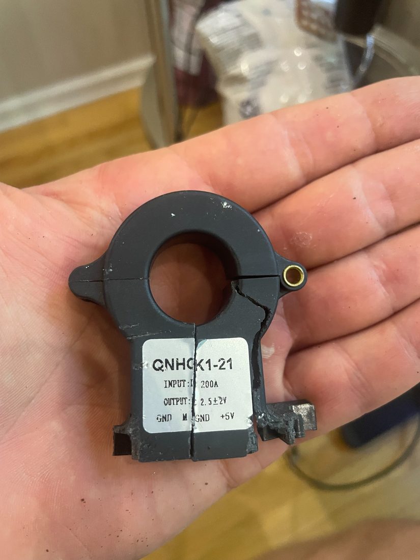
QNHCK1-21 after sawing lower body in half
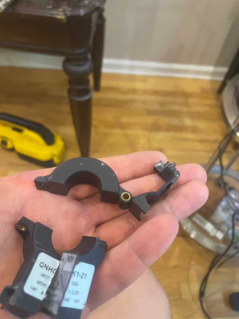
Split-core upper section separated from the lower body.
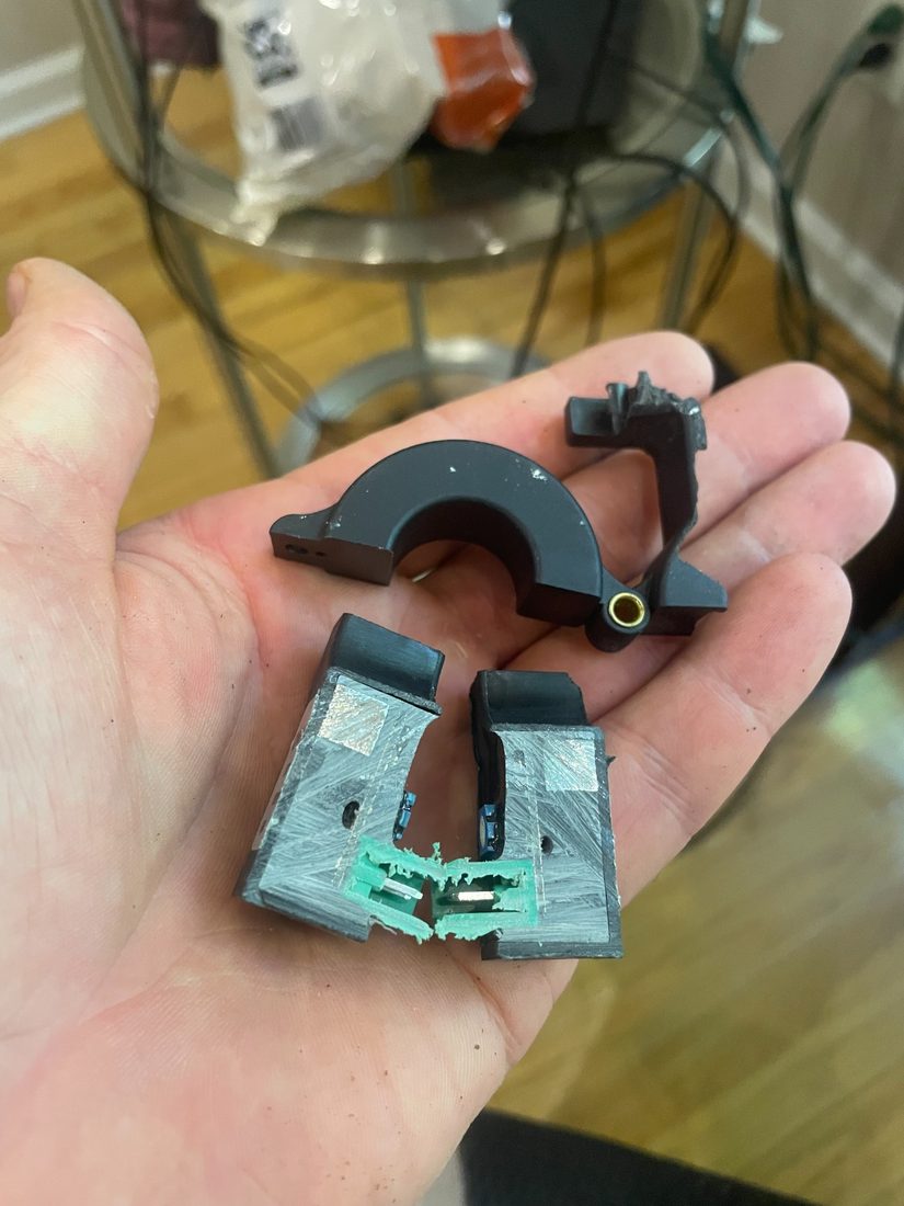
Lower body opened. Potting compound fills the housing; the bright rectangle high in each half is the sawn face of the Core, and the PCB and its green header are cut through below it.
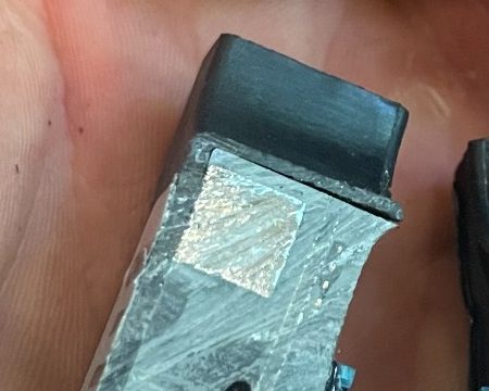
Detail of the same cut: the Core face, the molded bore wall above it, and potting compound all around.
Trimmer and connector details
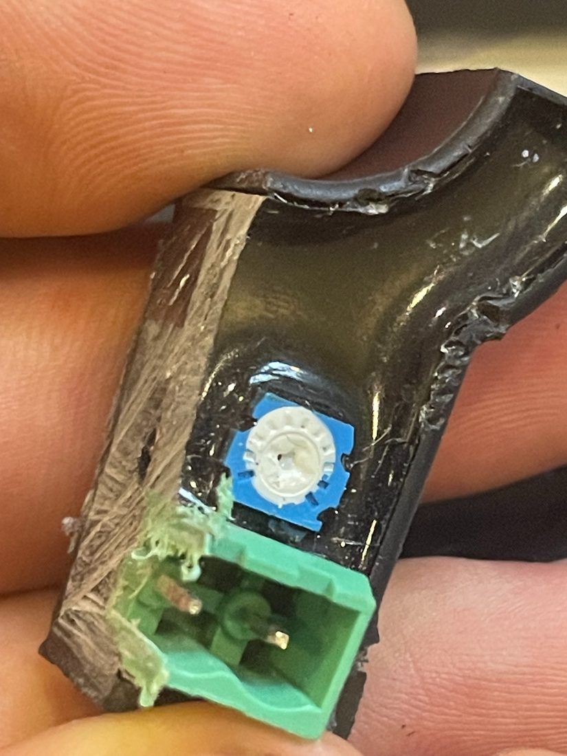
Trim Pot before disassembly. The white plug over its center is White Sealant.
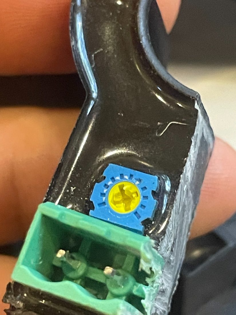
Yellow plastic adjustment rotor exposed after removing the white sealant.
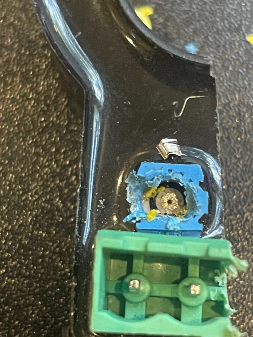
Trimmer disassembled further, exposing the metal wiper/contact mechanism beneath the rotor.
Comments on waterproofing
The potted PCB and Magnetic Core are good. The vulnerability is in the trim pots, which do not look sealed, but could be covered with silicone or epoxy. Next order, I will ask for them to be covered in manufacturing. The green connector is well sealed from the inside, but the plug interface is not. Fill with dielectric grease to create an assembly that is at least nominally splash proof. Careful application of silicone or 5 min epoxy could also seal the connector at some risk of difficult disassembly.